5.7 H: Terminal Functions
242 YASKAWA ELECTRIC SIEP C710616 27G YASKAWA AC Drive A1000 Technical Manual
Setting 30: PID integral reset
By configuring one of the digital inputs for PID integral reset (H1- = 30), the value of the integral component in PID
control will be reset to 0 whenever the terminal is closed. Refer to PID Block Diagram on page 170 for more details.
Setting 31: PID integral hold
By configuring a digital input for Integral Hold (H1- = 31), the value of the integral component of the PID control is
locked as long as the input is active. The PID controller resumes integral operation from the hold value as soon as the
integral hold input is released. Refer to PID Block Diagram on page 170 for more information on this
function.
Setting 32: Multi-Step Speed Reference 4
Used to select the multi-step speeds d1-09 to d1-16 in combination with the input terminal set for Multi-Step Speed 1, 2
and 3. Refer to d1-01 to d1-17: Frequency Reference 1 to 16 and Jog Fr
equency Reference on page 198.
Setting 34: PID soft starter cancel
A digital input configured as a PID soft starter cancel input (H1- = 34) can be used to enable or disable the PID soft
starter and thereby canceling the PID accel/decel time (b5-17). Refer to PID Block Diagram on page 170.
Setting 35: PID input level selection
Allows and input terminal to switch the sign of the PID input. Refer to PID Block Diagram on page 170 for details.
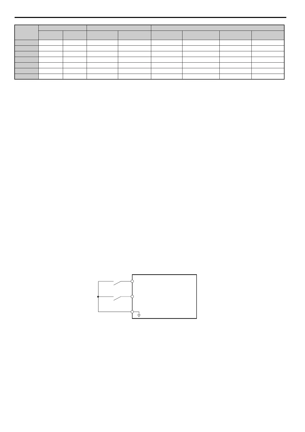
Setting 40, 41: Forward run, Reverse run command for 2-wire sequence
Configures the drive for a 2-wire sequence.
When an input terminal set to 40 closes, the drive
operates in the forward direction. When an input set for 41 closes, the
drive will operate in reverse. Closing both inputs at the same time will result in an external fault.
Note: 1. This function cannot be used simultaneously with settings 42 and 43.
2. The same functions are assigned to terminals S1 and S2 when the drive is initialized for 2-wire sequence.
Figure 5.66
Figure 5.66 Example Wiring Diagram for 2-Wire Sequence
Setting 42, 43: Run and direction command for 2-wire sequence 2
Sets the drive for 2-wire sequence 2.
When an input terminal programmed for 42 is closed, the drive will operate in
the direction selected. When the input
opens, the drive will stop. The input programmed for 43 selects the direction. If it is open, forward direction is selected.
If it is closed, reverse direction is selected.
Note: This function cannot be used simultaneously with settings 40 and 41.
Setting 44, 45, 46: Offset frequency 1, 2, 3
These inputs can be used to add offset frequencies d7-01, d7-02, and d7-03 to the frequency reference. Refer to d7-01 to
d7-03: Offset Frequency 1 to 3 on page 211 for details.
29 – – – – –
2A – – – – –
2B – – – – –
2C – – – – –
2D – – – – –
2E – – – – –
2F – – – – –
<1> Determine the terminal status for each fault, i.e., whether the terminal is normally open or normally closed.
<2> Determine whether detection for each fault should be enabled only during run or always detected.
Setting
Terminal Status <1> Detection Conditions <2> Stopping Method
N.O. N.C. Always Detected
Detected during
Run only
Ramp to Stop
(fault)
Coast to Stop
(fault)
Fast Stop
(fault)
Alarm Only
(continue running)
S1
S2
SC
Drive
Forward Run
Reverse Run
Digital Input Common