5.8 L: Protection Functions
YASKAWA ELECTRIC SIEP C710616 27G YASKAWA AC Drive A1000 Technical Manual 283
L3-02: Stall Prevention Level during Acceleration
Sets the output current level at which the Stall Prevention during acceleration is activated.
• Stalling may occur when the motor is rated at a smaller capacity than the drive and the Stall Prevention default settings
are used. Set L3-02 as appropriate if stalling occurs.
• When operating the motor in
the constant power range, also set parameter L3-03.
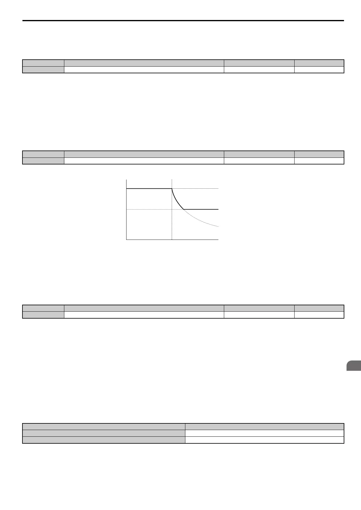
L3-03: Stall Prevention Limit during Acceleration
The Stall Prevention level is automatically reduced when the motor is operated in the constant power range. L3-03 sets
the lower limit for this reduction as a percentage of the drive rated current.
Figure 5.103
Figure 5.103 Stall Prevention Level and Limit During Acceleration
L3-04: Stall Prevention Selection during Deceleration
Stall Prevention during deceleration can control the deceleration based on the DC bus voltage and prevent an overvoltage
fault caused by high inertia or rapid deceleration.
Setting 0: Disabled
When this setting is used, the drive decelerates according to the set deceleration time. With high inertia loads or rapid
deceleration, an overvoltage (ov) fault may occur. In this case use dynamic braking options or switch to another L3-04
selection.
Setting 1: General-purpose Stall Prevention
With this setting the drive tries to decelerate within the set deceleration time. When the DC bus voltage exceeds the Stall
Prevention level, the drive pauses deceleration. Deceleration continues as soon as the DC bus voltage drops below that
level. Stall Prevention may be triggered repeatedly to avoid an overvoltage fault. The DC bus voltage level for Stall
Prevention depends on the input voltage setting E1-01.
Note: 1. This setting should not be used in combination with a Dynamic Braking Resistor or other dynamic braking options. If Stall
Prevention during deceleration is enabled, it will be triggered before the braking resistor option can operate.
2. This
method may lengthen the total deceleration time compared to the set value. If this is not appropriate for the application consider
using a dynamic braking option.
No.
<1> The upper limit and default value is determined by the duty rating and the carrier frequency derating selection (C6-01 and L8-38 respectively).
Name Setting Range Default
L3-02 Stall Prevention Level during Acceleration 0 to 150% <1> <1>
No. Name Setting Range Default
L3-03 Stall Prevention Limit during Acceleration 0 to 100% 50%
No.
<1> Settings 3 through 5 are not available in OLV/PM. Settings 2 through 5 are not available in AOLV/PM and CLV/PM.
<2> The setting range is 0 to 2, 4, or 5 for models CIMR-A4A0930 to 4A1200.
Name Setting Range Default
L3-04 Stall Prevention Selection During Deceleration 0 to 5 <1> <2> 1
Drive Input Voltage Stall Prevention Level during Deceleration
200 V Class 377 Vdc
400 V Class 754 Vdc
Stall Prevention level during Acceleration
Output frequency
L3-03
E1-06
Base frequency
L3-02
 Loading...


