5.8 L: Protection Functions
286 YASKAWA ELECTRIC SIEP C710616 27G YASKAWA AC Drive A1000 Technical Manual
L3-17: Target DC Bus Voltage for Overvoltage Suppression and Stall Prevention
Sets the target DC bus voltage target level used by the overvoltage suppression function (L3-11 = 1), Intelligent Stall
Prevention during deceleration (L3-04 = 2).
L3-20: DC Bus Voltage Adjustment Gain
Determines the proportional gain used by overvoltage suppression (L3-11 = 1), Single Drive KEB 2 (L2-29 = 1), KEB
Ride Thru 2 (H1- = 7A or 7B) and Intelligent Stall Prevention during deceleration
(L3-04 = 2) in order to control the
DC bus voltage.
Adjustment for Single Drive KEB 2 (L2-29 = 1) and Intelligent Stall Prevention During Deceleration
• Increase this setting slowly in steps of 0.1 if overvoltage or undervoltage occurs at the beginning of deceleration.
• If this setting is too high, then a fair amount of speed or torque r
ipple can result.
Adjustment for Overvoltage Suppression
• Increase this setting slowly in steps of 0.1 if overvoltage suppression is enabled (L3-11 = 1) and a sudden increase in a
regenerative load results in an overvoltage (ov) fault.
• If this setting is too high, excessive
speed or torque ripple can result.
L3-21: Accel/Decel Rate Calculation Gain
Determines the proportional gain used by overvoltage suppression (L3-11 = 1), Single Drive KEB 2 (L2-29 = 1), and
Intelligent Stall Prevention during deceleration (L3-04 = 2) in order to calculate acceleration and deceleration rates.
Adjustment for Single Drive KEB 2 (L2-29 = 1) and Intelligent Stall Prevention During Deceleration
• Reduce L3-21 in steps of 0.05 if there is a fairly large speed or current ripple.
• Small reductions of L3-21can also help solve pro
blems with overvoltage and overcurrent.
• Decreasing this setting too much can result
in a slow DC bus voltage control response and may also lengthen
deceleration times beyond optimal levels.
Adjustment for Overvoltage Suppression
• Increase this setting in steps of 0.1 if overvoltage occurs as a result of a regenerative load when overvoltage
suppression is enabled (L3-11 = 1).
• If there is a fairly large speed ripple w
hen overvoltage suppression is enabled, then decrease L3-21 in steps of 0.05.
L3-22: Deceleration Time at Stall Prevention during Acceleration
Sets the brief deceleration time used when stalling occurs while accelerating a PM motor. When set to 0, this function is
disabled and the drive will decelerate at the selected deceleration time when stalling occurs.
The function is effective only in Open Loop Vector Control for PM motors and if parameter L3-01 is set to
1.
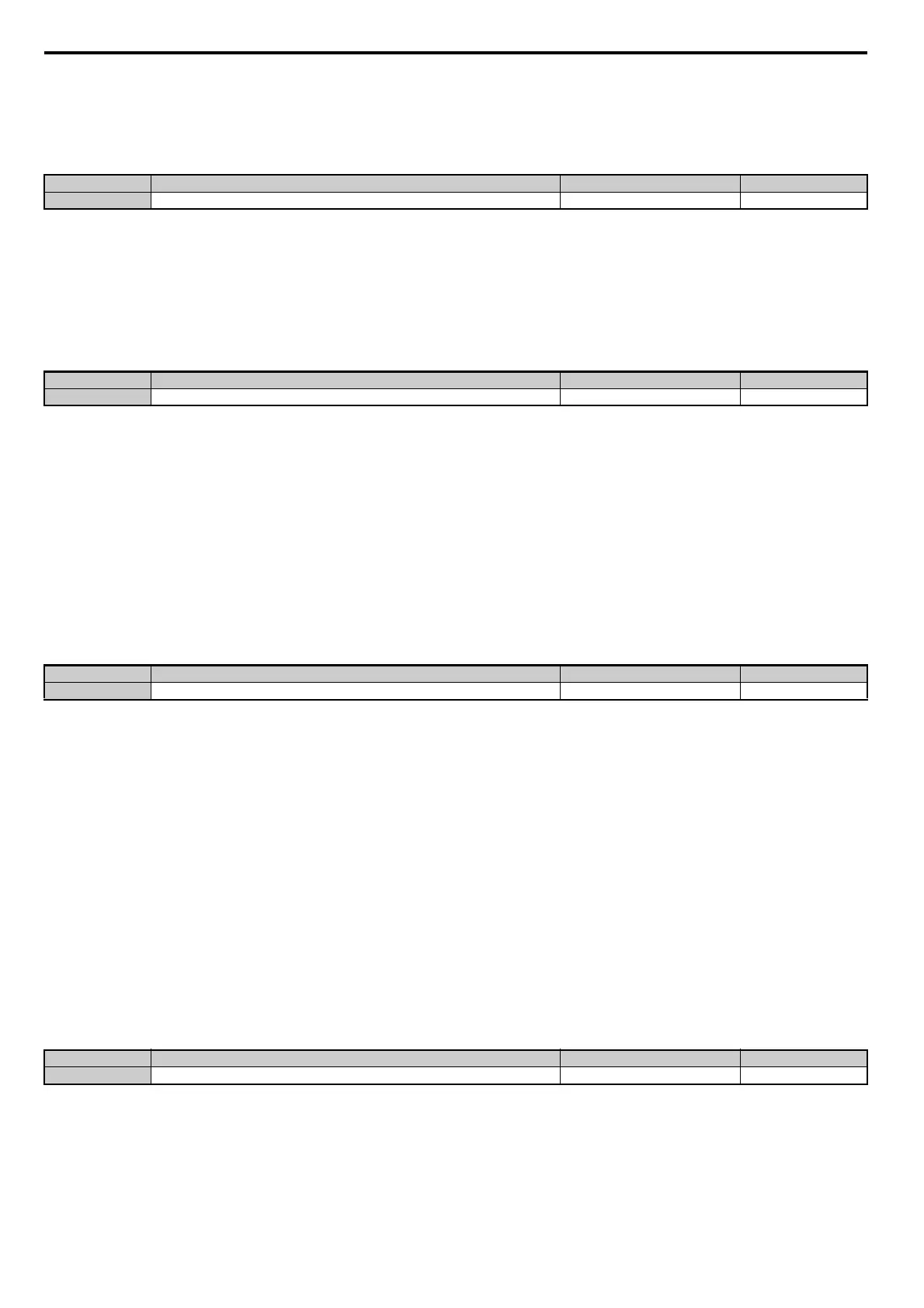
No.
<1> Values are specific to 200 V class drives. Double the value for 400 V class drives.
<2> This value is initialized when E1-01 is changed.
Name Setting Range Default
L3-17 Target DC Bus Voltage for Overvoltage Suppression and Stall Prevention 150 to 400 Vdc <1> 375 Vdc <1> <2>
No. Name Setting Range Default
L3-20 DC Bus Voltage Adjustment Gain 0.00 to 5.00 Determined by A1-02
No.
<1> This value is reset to its default value when the control mode is changed (A1-02). The value shown here is for Open Loop Vector Control.
Name Setting Range Default
L3-21 Accel/Decel Rate Calculation Gain 0.10 to 10.00 <1>
No. Name Setting Range Default
L3-22 Deceleration Time at Stall Prevention During Acceleration 0.0 to 6000.0 s 0.0 s