6.4 Fault Detection
340 YASKAWA ELECTRIC SIEP C710616 27G YASKAWA AC Drive A1000 Technical Manual
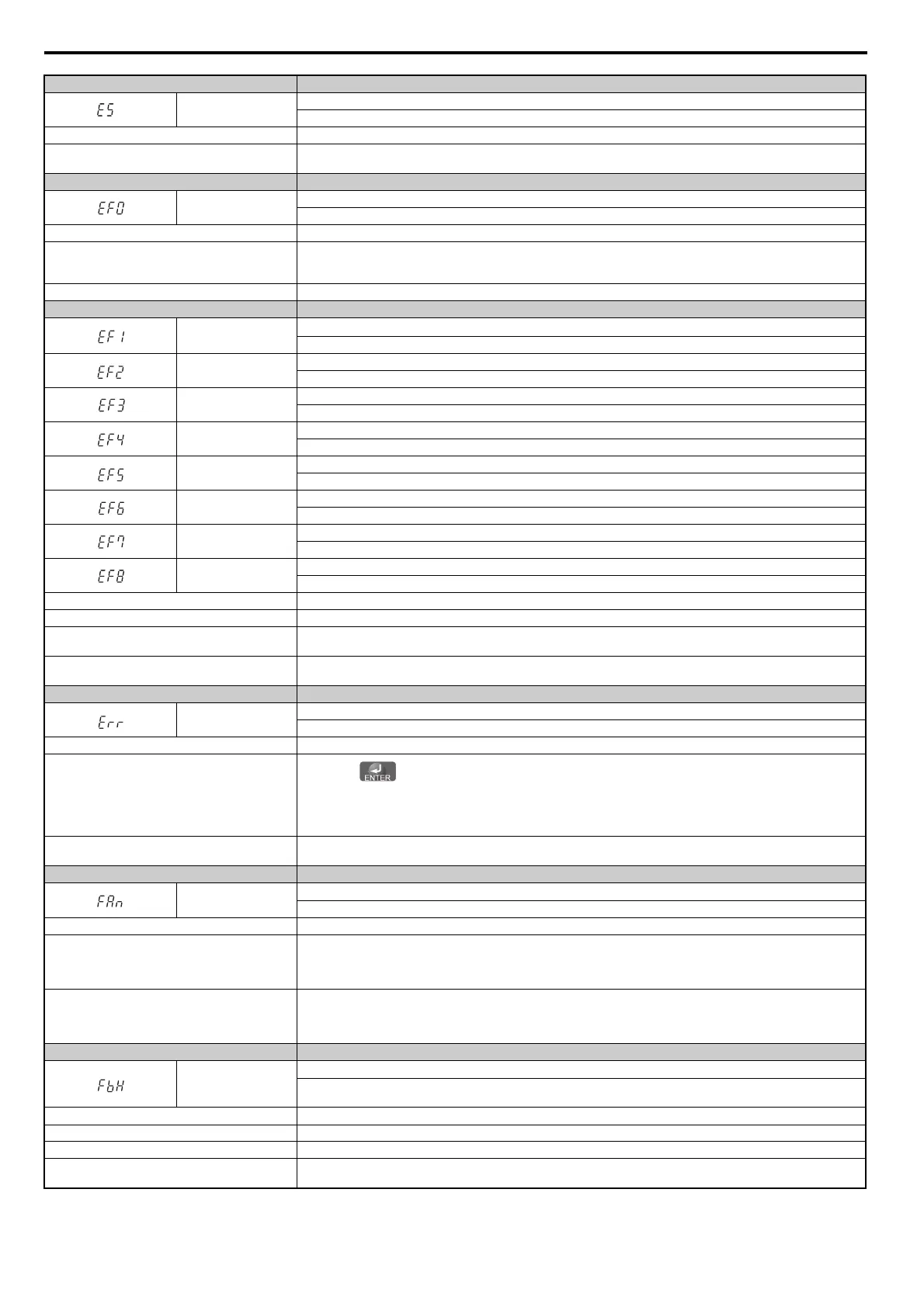
Digital Operator Display Fault Name
E5
MECHATROLINK Watchdog Timer Error
The watchdog has timed out.
Cause Possible Solution
Data has not been received from the PLC, triggering the
watchdog timer.
Execute DISCONNECT or ALM_CLR, then issue a CONNECT command or SYNC_SET command and proceed to phase 3.
Digital Operator Display Fault Name
EF0
Option Card External Fault
An
external fault condition is present.
Cause Possible Solution
An external fault was received from
the PLC with other
than F6-03 = 3 “alarm only” (the drive continued to run
after external fault).
• Remove the cause of the external fault.
• Remove the external fault input from the PLC.
Problem with the PLC program. Check the PLC program and correct problems.
Digital Operator Display Fault Name
EF1
External Fault (input terminal S1)
Ex
ternal fault at multi-function input terminal S1.
EF2
External Fault (input terminal S2)
Ex
ternal fault at multi-function input terminal S2.
EF3
External Fault (input terminal S3)
Ex
ternal fault at multi-function input terminal S3.
EF4
External Fault (input terminal S4)
Ex
ternal fault at multi-function input terminal S4.
EF5
External Fault (input terminal S5)
Ex
ternal fault at multi-function input terminal S5.
EF6
External Fault (input terminal S6)
Ex
ternal fault at multi-function input terminal S6.
EF7
External Fault (input terminal S7)
Ex
ternal fault at multi-function input terminal S7
EF8
External Fault (input terminal S8)
Ex
ternal fault at multi-function input terminal S8
Cause Possible Solution
An external device has tripped an alarm function. Remove the
cause of the external fault and reset the fault.
Wiring is incorrect.
• Ensure the signal lines have been connected properly to the
terminals assigned for external fault detection (H1- = 20 to 2B).
• Reconnect the signal line.
Incorrect setting of multi-function contact inputs.
• Check if the any unused t
erminals are set for H1- = 20 to 2B (External Fault).
• Change the terminal settings.
Digital Operator Display Fault Name
Err
EEPROM Write Error
Dat
a cannot be written to the EEPROM.
Cause Possible Solution
Noise has corrupted data whi
le writing to the EEPROM.
•Press the button.
• Correct the parameter setting.
• Cycle power to the drive. Refer to Diagnosing and Resetting Faults on page 366.
• Replace either the control board or the entire drive. For instructio
ns on replacing the control board, contact YASKAWA or your
nearest sales representative.
Hardware problem.
Replace either the control board or the entire drive. For instructions on replacing the control board, contact YASKAWA or your
nearest sales representative.
Digital Operator Display Fault Name
FAn
Internal Fan Fault
Fan or m
agnetic contactor failed (detected when L8-32 = 0 to 2).
Cause Possible Solution
Internal cooling fan has malfunctioned (models 2A0360,
2A0415, 4A0362 to 4A1200).
Cycle power to the drive and see if the fault is still present.
Check if the fan is operating or not.
Verify the cumulative operation time of the fan using monitor U4-03, and the fan maintenance timer in U4-04.
If the cooling fan has passed its expected performance life or is damaged in some way, replace the fan.
Fault detected in the internal cooling fan or magnetic
contactor to the power supply (models 2A0250 to
2A0415, 4A0165 to 4A1200).
Cycle power to the drive and see if the fault is still present.
If the fault still occurs, either replace the control circuit board or the entire unit.
For instructions on replacing the power board, contact the YASKAWA sales office directly or your nearest YASKAWA
representative.
Digital Operator Display Fault Name
FbH
Excessive PID Feedback
PID feed
back input is greater than the level set b5-36 for longer than the time set to b5-37. To enable fault detection, set b5-12 =
2 or 5.
Cause Possible Solution
Parameters are not set appropriately. Check th
e settings of parameters b5-36 and b5-37.
Wiring for PID feedback is incorrect. Correct the wiring.
There is a problem with the feedback sensor.
• Check the sensor on the control side.
• Replace the sensor if damaged.