6.4 Fault Detection
YASKAWA ELECTRIC SIEP C710616 27G YASKAWA AC Drive A1000 Technical Manual 339
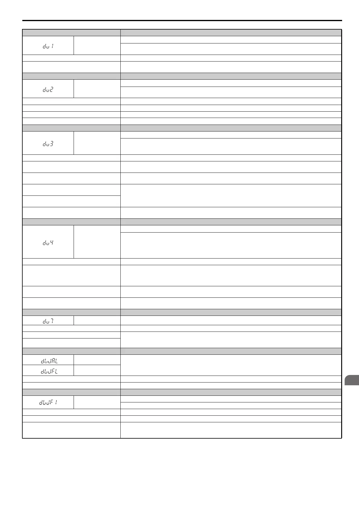
Digital Operator Display Fault Name
dv1
Z Pulse Fault
The m
otor turned one full rotation without the Z pulse being detected.
Note: Available in CLV/PM control mode only.
Cause Possible Solution
PG encoder is not connected, not
wired properly, or is
damaged.
• Make sure the PG encoder is properly connected and all shielded lines are properly grounded.
• If the problem continues after cycling power, then replace either the PG option card or the PG encoder itself.
Digital Operator Display Fault Name
dv2
Z Pulse Noise Fault Detection
The Z
pulse is out of phase by more than 5 degrees for the number of times specified in parameter F1-17.
Note: Available in CLV/PM control mode only.
Cause Possible Solution
Electrical signal interference along the PG cable. Separate the PG cable lines from the source of the noise (very possibly drive output wiring).
PG cable is not wired properly. Rewire the PG encoder and make sure all shielded lines are properly grounded.
PG option card or the PG encoder is damaged. If the problem continues after cycling power, then replace either the PG option card or the PG encoder itself.
Digital Operator Display Fault Name
dv3
Inversion Detection
The torque ref
erence and acceleration are in opposite directions from one another (one is in reverse and the other is forward)
while at the same time the speed reference and actual motor speed differ by over 30% for the number of pulses set to F1-18.
Note: Available in CLV/PM control mode only.
Cause Possible Solution
The Z pulse offset is not set properly to E5-11.
S
et the value for to E5-11 as specified on the motor nameplate. Replacing the PG encoder or changing the application so that
the motor rotates in reverse instead requires readjustment of the Z pulse offset. (T2-01 = 3)
An external force on the load side has caused the motor
to move.
• Make sure the motor is rotating in the right direction.
• Look for any problems on the load side that might be c
ausing the motor to rotate in the opposite direction.
Electrical signal interference along the PG cable
affecting the A or B pulse.
Rewire the PG encoder and make sure all lines including shielded line are properly connected.
PG encoder is disconnected, not wired properly, or the
PG option card or PG itself is damaged.
Rotational direction for the PG encoder set to F1-05 is
the opposite of the order of the motor lines.
Make sure motor lines for each phase (U, V, W) are connected properly.
Digital Operator Display Fault Name
dv4
Inversion Prevention Detection
Puls
es indicate that the motor is rotating in the opposite direction of the speed reference. Set the number of pulses to trigger
inverse detection to F1-19.
Note: 1. Disable inverse detection in applications where the motor may rotate in the opposite direction of the speed reference.
Setting F1-19 to 0 disables this feature.
2. Available in CLV/PM control mode only.
Cause Possible Solution
The Z pulse offset is not set properly to E5-11.
• Set the value for to E
5-11 as specified on the motor nameplate.
• If the problem continues after cycling power, then replace either th
e PG option card or the PG encoder itself. Replacing the PG
encoder or changing the application so that the motor rotates in reverse instead requires readjustment of the Z-pulse offset.
(T2-01 = 3)
Electrical signal interference along the PG cable
af
fecting the A or B pulse.
• Make sure the motor is rotating in the correct direction.
• Look for any problems on the load side that might be c
ausing the motor to rotate in the opposite direction.
PG encoder is disconnected, not
wired properly, or the
PG option card or PG itself is damaged.
• Rewire the PG encoder and make sure all lines including shielded line are properly connected.
• If the problem continues after cycling power, then replace either the PG option card or the PG encoder itself.
Digital Operator Display Fault Name
dv7
Polarity Judge Timeout
Cause Possible Solution
Disconnection in the motor coil winding. • Measure the motor line-to-line resistance and replace the motor if the motor coil winding is open.
• Check for loose terminals. Apply the tightening torque spe
cified in this manual to fasten the terminals.
Refer to Wire Size on page 85.
Loose output terminals.
Digital Operator Display Fault Name
dWAL
DriveWorksEZ Fault
dWFL
Cause Possible Solution
Fault output by DriveWorksEZ Correct whatever caused the fault.
Digital Operator Display Fault Name
dWF1
EEPROM Memory DriveWorksEZ Data Error
There is
an error in the DriveWorksEZ program saved to EEPROM.
Cause Possible Solution
Problem with EEPROM data. Reinitialize the drive (A1-03 = 2220,
3330) and then download the DriveWorksEZ program again.
There is an error in EEPROM control circuit.
• Turn the power off and check the connection between the control board and the drive.
• If the problem continues, replace either the control board or the ent
ire drive and then download the DriveWorksEZ program.
For instructions on replacing the control board, contact YASKAWA or your nearest sales representative.