6.5 Alarm Detection
YASKAWA ELECTRIC SIEP C710616 27G YASKAWA AC Drive A1000 Technical Manual 351
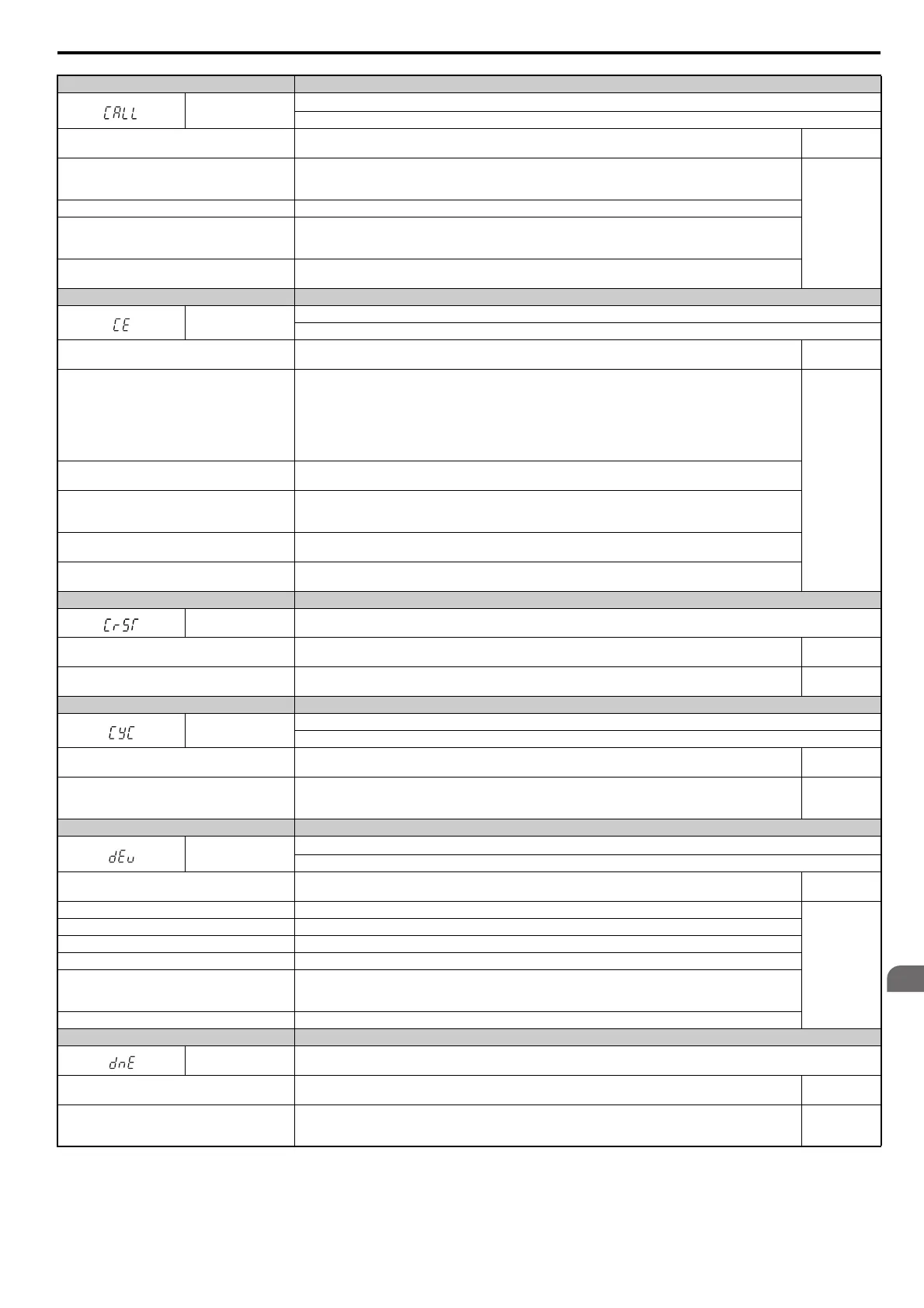
Digital Operator Display Minor Fault Name
CALL
Serial Communication Transmission Error
C
ommunication has not yet been established.
Cause Possible Solutions
Minor Fault
(H
2- = 10)
Communications wiring is faulty, there is a short
ci
rcuit, or something is not connected properly.
• Check for wiring errors.
• Correct the wiring.
• Check for disconnected cables and short circuits. Repair as needed.
YES
Programming error on the master side. Check communicat
ions at start-up and correct programming errors.
Communications circuitry is damaged.
• Perform a self-diagnostics check.
• If the problem continues, replace either t
he control board or the entire drive. For instructions on replacing the
control board, contact YASKAWA or your nearest sales representative.
Termination resistor setting is incorrect.
A termination resistor must be installed at both ends of a communication line. Slave drives must have the internal
termination resistor switch set correctly. Place DIP switch S2 to the ON position.
Digital Operator Display Minor Fault Name
CE
MEMOBUS/Modbus Communication Error
C
ontrol data was not received correctly for two seconds.
Cause Possible Solutions
Minor Fault
(H
2- = 10)
A data error occurred due to noise.
• Check options available to minimize the effects of noise.
• Take steps to counteract noise in the control circui
t wiring, main circuit lines, and ground wiring.
• Reduce noise on the controller side.
• Use surge absorbers for the magnetic contactors or oth
er components that may be causing the disturbance.
• Use only recommended shielded line. Ground the shield on t
he controller side or on the drive input power side.
• Separate all wiring for comm. devices from drive input power
lines. Install an EMC noise filter to the drive input
power supply.
YES
Communication protocol is incompatible.
• Check the H5 parameter settings as well as the prot
ocol setting in the controller.
• Ensure settings are compatible.
The CE detection time (H5-09) is set shorter than the
tim
e required for a communication cycle to take
place.
• Check the PLC.
• Change the software settings in the PLC.
• Set a longer CE detect
ion time (H5-09).
Incompatible PLC software settings or there is a
har
dware problem.
• Check the PLC.
• Remove the cause of the error on the controller side.
Communications cable is discon
nected or damaged.
• Check the connector to make sur
e the cable has a signal.
• Replace the communications cable.
Digital Operator Display Minor Fault Name
CrST
Cannot Reset
Cause Possible Solutions
Minor Fault
(H2- = 10)
A fault reset command was entered while the Run
co
mmand was still present.
• Ensure that a Run command cannot be entered from the external terminals or option card during fault reset.
• Turn off the Run command.
YES
Digital Operator Display Minor Fault Name
CyC
MECHATROLINK Comm. Cycle Setting Error
Comm. Cycl
e Setting Error was detected.
Cause Possible Solutions
Minor Fault
(H
2- = 10)
The controller is using a comm. cycle beyond the
al
lowable setting range for the MECHATROLINK
option.
Set the comm. cycle for the upper controller within the allowable setting range for the MECHATROLINK option.
YES
Digital Operator Display Minor Fault Name
dEv
Speed Deviation (when using a PG option card and AOLV/PM without PG)
T
he deviation between the speed reference and speed feedback is greater than the setting in F1-10 for longer than the time in F1-11.
Cause Possible Solutions
Minor Fault
(H
2- = 10)
Load is too heavy Reduce the load.
YES
Acceleration and deceleration times are set too
short. Increase the acceleration and deceleration times (C1-01 through C1-08).
The load is locked up. Check the machine.
Parameter settings are inappropriate. Check the settings of parameters F1-10 and F1-11.
Incorrect speed feedback scaling if terminal RP is
used as speed feedback input in V/f Control.
• Set H6-02 to value of the speed feedback signal frequency when the motor runs at the maximum speed.
• Adjust the speed feedback signal usi
ng parameters H6-03 through H6-05.
• Make sure the speed feedback signal frequency do
es not exceed he maximum input frequency of terminal RP.
The motor brake engaged. Ensure the brake releases properly.
Digital Operator Display Minor Fault Name
dnE Drive Disabled
Cause Possible Solutions
Minor Fault
(H2- = 10)
“Drive Enable” is set to a multi-function contact
inpu
t (H1- = 6A) and that signal was switched
off.
Check the operation sequence. YES
 Loading...


