B.3 Parameter Table
YASKAWA ELECTRIC SIEP C710616 27G YASKAWA AC Drive A1000 Technical Manual 475
F1-12
(38BH)
PG 1 Gear Teeth 1
Sets the gear ratio between the motor shaft and the encoder (PG).
A gear ratio of 1 will be used if either of these parameters is set to 0.
Default: 0
Min: 0
Max: 1000
226
F1-13
(38CH)
PG 1 Gear Teeth 2
Default: 0
Min: 0
Max: 1000
226
F1-14
(38DH)
PG Open-Circuit Detection Time
Sets the time required to trigger a PG Open fault (PGo).
Default: 2.0 s
Min: 0.0 s
Max: 10.0 s
225
F1-18
(3ADH)
dv3 Detection Selection
0: Disabled
1: Enabled
Default: 10
Min: 0
Max: 10
227
F1-19
(3AEH)
dv4 Detection Selection
0: Disabled
n: Number of pulses that the A and B pulse are reversed that triggers dv4 detection.
Default: 128
Min: 0
Max: 5000
227
F1-20
(3B4H)
PG Option Card Disconnect
Detection 1
0: Disabled
1: Enabled
Default: 1
Min: 0
Max: 1
227
F1-21
(3BCH)
PG 1 Signal Selection
0: A pulse detection
1: AB pulse detection
Default: 0
Min: 0
Max: 1
227
F1-30
(3AAH)
PG Card Option Port for Motor 2
Selection
Sets the port for the PG option card used by motor 2.
0: CN5-C
1: CN5-B
Default: 1
Min: 0
Max: 1
227
F1-31
(3B0H)
PG 2 Pulses Per Revolution
Sets the number of pulses for a PG option card connected to port CN5-B.
Default: 1024 ppr
Min: 1 ppr
Max: 60000 ppr
225
F1-32
(3B1H)
PG 2 Rotation Selection
0: Pulse A leads
1: Pulse B leads
Default: 0
Min: 0
Max: 1
226
F1-33
(3B2H)
PG 2 Gear Teeth 1
Sets the gear ratio between the motor shaft and the encoder (PG).
A gear ratio of 1 will be used if either of these parameters is set to 0.
Default: 0
M
in: 0
Max: 1000
226
F1-34
(3B3H)
PG 2 Gear Teeth 2
Default: 0
Min: 0
Max: 1000
226
F1-35
(3BEH)
PG 2 Division Rate for Pulse
Monitor
Sets the division ratio for the pulse monitor used of the PG option card 2 installed to connector
CN5-B. By setting for a three-digit number: xyz, the division ratio becomes = [(1 + x) / yz].
Note: Values 033 to 101 are not available.
Default: 001
Min: 001
Max: 132
226
F1-36
(3B5H)
PG Option Card Disconnect
Detection 2
0: Disabled
1: Enabled
Default: 1
Min: 0
Max: 1
227
F1-37
(3BDH)
PG 2 Signal Selection
0: A pulse detection
1: AB pulse detection
Default: 0
Min: 0
Max: 1
227
F1-50
(3D2H)
Encoder Selection
Selects the encoder connected the PG-F3 option.
0: EnDat 2.1/01, 2.2/01 Serial Communication + Sin/Cos
1: EnDat 2.2/22 Serial Communication
2: Hiperface
Note: 1. This parameter is not available with models CIMR-A4A0930 and 4A1200.
2. The use of EnDat2.2/22 encoders requires a PG-F3 option with software version 0102
or later. To identify the PG-F3 software version refer to the PG-F3 labeling in the field
designated “C/N” (S + four digit number).
Default: 0
Min: 0
Max: 2
228
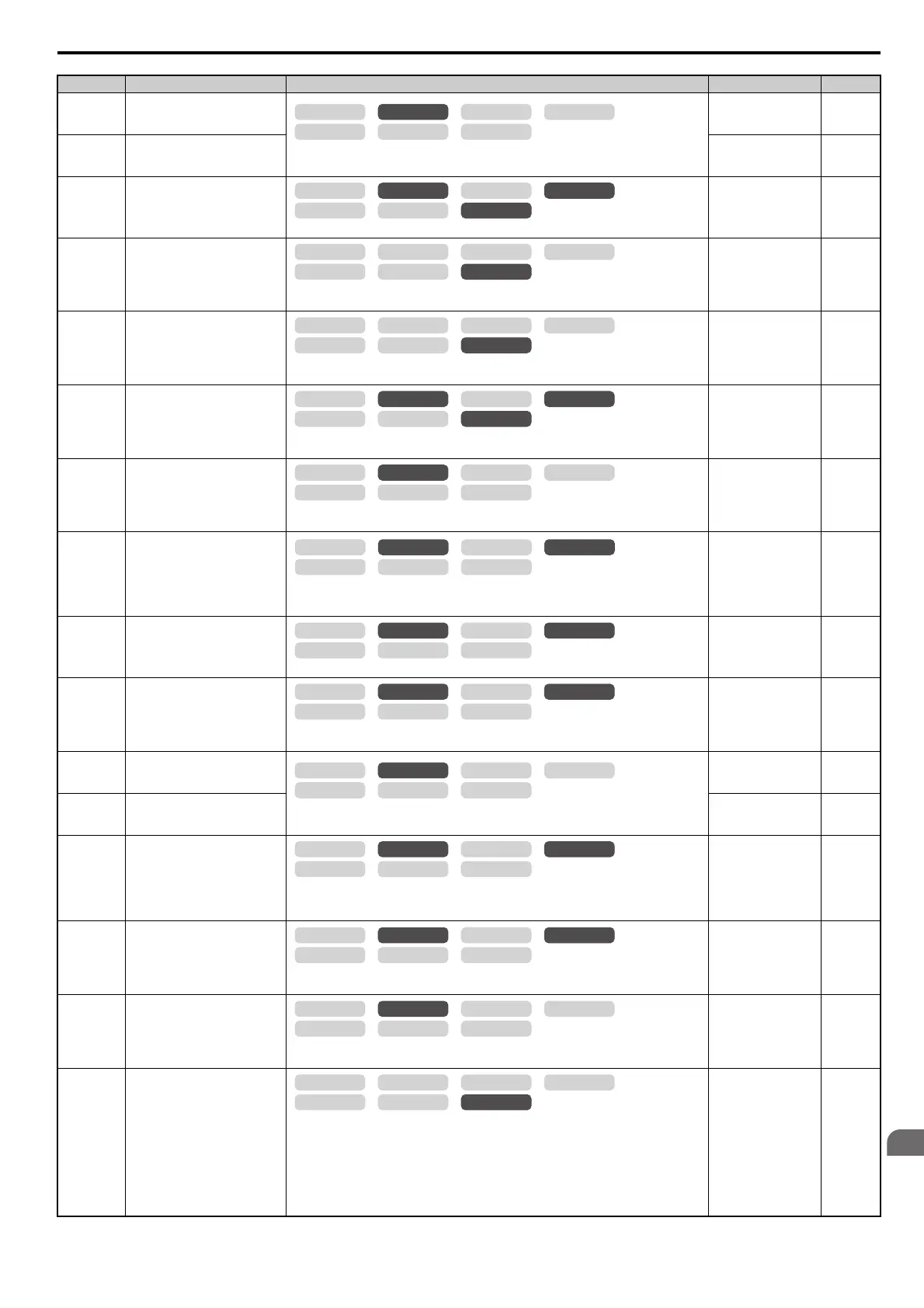
No.(Addr.) Name Description Setting Page
OLV/PM AOLV/PM
CLV
V/f w/PG
CLV/PM
V/f OLV
OLV/PM AOLV/PM
CLV
V/f w/PG
CLV/PM
V/f OLV
OLV/PM AOLV/PM
CLV
V/f w/PG
CLV/PM
V/f OLV
OLV/PM AOLV/PM
CLV
V/f w/PG
CLV/PM
V/f OLV
OLV/PM AOLV/PM
CLV
V/f w/PG
CLV/PM
V/f OLV
OLV/PM AOLV/PM
CLV
V/f w/PG
CLV/PM
V/f OLV
OLV/PM AOLV/PM
CLV
V/f w/PG
CLV/PM
V/f OLV
OLV/PM AOLV/PM
CLV
V/f w/PG
CLV/PM
V/f OLV
OLV/PM AOLV/PM
CLV
V/f w/PG
CLV/PM
V/f OLV
OLV/PM AOLV/PM
CLV
V/f w/PG
CLV/PM
V/f OLV
OLV/PM AOLV/PM
CLV
V/f w/PG
CLV/PM
V/f OLV
OLV/PM AOLV/PM
CLV
V/f w/PG
CLV/PM
V/f OLV
OLV/PM AOLV/PM
CLV
V/f w/PG
CLV/PM
V/f OLV
OLV/PM AOLV/PM
CLV
V/f w/PG
CLV/PM
V/f OLV