B.3 Parameter Table
476 YASKAWA ELECTRIC SIEP C710616 27G YASKAWA AC Drive A1000 Technical Manual
F2: Analog Input Card (AI-A3)
F3: Digital Input Card (DI-A3)
F4: Analog Monitor Card (AO-A3)
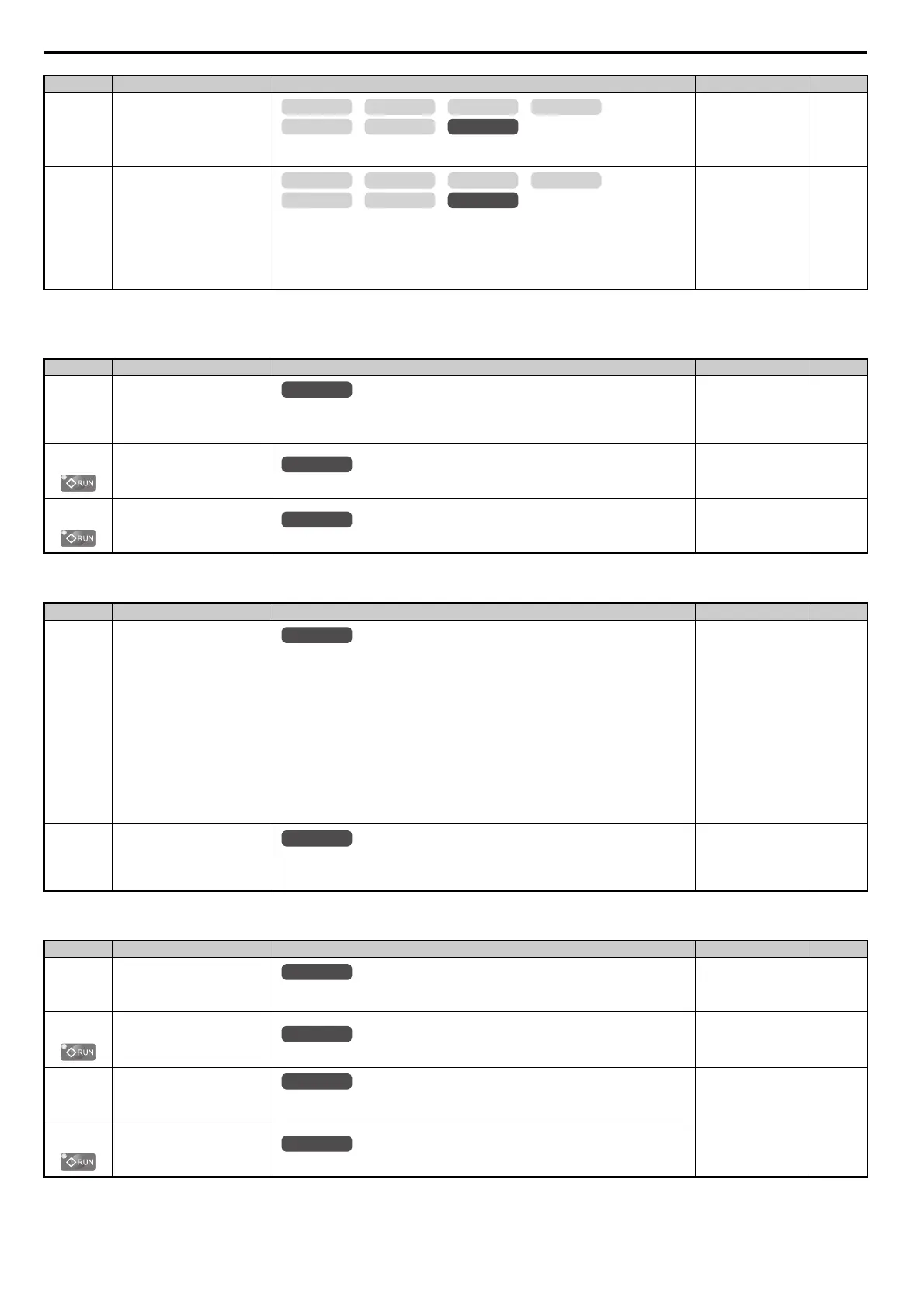
F1-51
(3D3H)
PGoH Detection Level
Sets the level for detecting PG Hardware Fault (PGoH). Available when F1-20 = 1
Note: This parameter is not available with models CIMR-A4A0930 and 4A1200.
Default: 80%
Min: 1%
Max: 100%
228
F1-52
(3D4H)
Communication Speed of Serial
Encoder Selection
Selects the communication speed between the PG-F3 option and serial encoder.
0: 1M bps/9600 bps (EnDat 2.2/22 / Hiperface)
1: 500k bps/19200 bps (EnDat 2.2/22 / Hiperface)
2: 1M bps/38400 bps (EnDat 2.2/22 / Hiperface)
3: 1M bps/38400 bps (EnDat 2.2/22 / Hiperface)
Note: This parameter is not available with models CIMR-A4A0930 and 4A1200.
Default: 0
Min: 0
Max: 3
228
<10> Default setting is determined by the control mode (A1-02).
No.(Addr.) Name Description Setting Page
F2-01
(38FH)
Analog Input Option Card
Operation Selection
0: Option card input terminals V1, V2, and V3 replace drive input terminals A1, A2, and A3.
1: Input signals to terminals V1, V2, and V3 are added together to create the frequency
reference.
Default: 0
Min: 0
Max: 1
228
F2-02
(368H)
Analog Input Option Card Gain
Sets the gain for the input signal to the analog card.
Default: 100.0%
Min: -999.9%
Max: 999.9%
229
F2-03
(369H)
Analog Input Option Card Bias
Sets the bias for the input signal to the analog card.
Default: 0.0%
Min: -999.9%
Max: 999.9%
229
No.(Addr.) Name Description Setting Page
F3-01
(390H)
Digital Input Option Card Input
Selection
0: BCD, 1% units
1: BCD, 0.1% units
2: BCD, 0.01% units
3: BCD, 1 Hz units
4: BCD, 0.1 Hz units
5: BCD, 0.01 Hz units
6: BCD customized setting (5 digit), 0.02 Hz units
7: Binary input
The unit and the setting range are determined by F3-03.
F3-03 = 0: 255/100% (-255 to+255)
F3-03 = 1: 40961/100% (-4095 to +4095)
F3-03 = 2: 30000/100% (-33000 to+33000)
When the digital operator units are set to be displayed in Hertz or user-set units (o1-03 = 2 or 3),
the units for F3-01 are determined by parameter o1-03.
Default: 0
Min: 0
Max: 7
229
F3-03
(3B9H)
Digital Input Option DI-A3 Data
Length Selection
0: 8 bit
1: 12 bit
2: 16 bit
Default: 2
Min: 0
Max: 2
229
No.(Addr.) Name Description Setting Page
F4-01
(391H)
Terminal V1 Monitor Selection
Sets the monitor signal for output from terminal V1. Set this parameter to the last three digits of
the desired U- monitor. Some U parameters are available only in certain control modes.
Default: 102
Min: 000
Max: 999
230
F4-02
(392H)
Terminal V1 Monitor Gain
Sets the gain for voltage output via terminal V1.
Default: 100.0%
Min: -999.9%
Max: 999.9%
230
F4-03
(393H)
Terminal V2 Monitor Selection
Sets the monitor signal for output from terminal V2. Set this parameter to the last three digits of
the desired U- monitor. Some U parameters are available only in certain control modes.
Default: 103
Min: 000
Max: 999
230
F4-04
(394H)
Terminal V2 Monitor Gain
Sets the gain for voltage output via terminal V2.
Default: 50.0%
Min: -999.9%
Max: 999.9%
230
No.(Addr.) Name Description Setting Page
OLV/PM AOLV/PM
CLV
V/f w/PG
CLV/PM
V/f OLV
OLV/PM AOLV/PM
CLV
V/f w/PG
CLV/PM
V/f OLV
All Modes
All Modes
All Modes
All Modes
All Modes
All Modes
All Modes