B.3 Parameter Table
YASKAWA ELECTRIC SIEP C710616 27G YASKAWA AC Drive A1000 Technical Manual 489
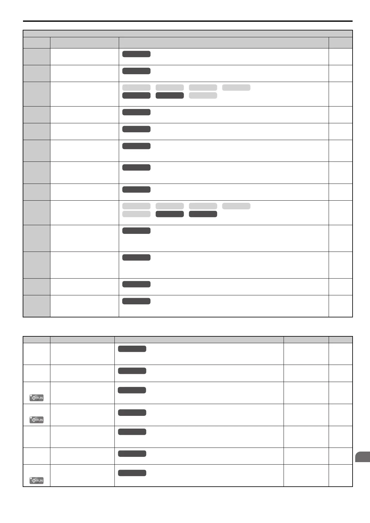
H3: Multi-Function Analog Inputs
3F PID Feedback High
Closed: The PID feedback level is too high.
255
4A During KEB Ride-Thru
Closed: KEB Ride-Thru is being performed.
255
4B During Short-Circuit Braking
Closed: Short Circuit Braking is active.
255
4C During Fast Stop
Closed: A Fast Stop command has been entered from the operator or input terminals.
255
4D oH Pre-alarm Time Limit
Closed: oH pre-alarm time limit has passed.
255
4E Braking Transistor Fault (rr)
Closed: The built-in dynamic braking transistor failed.
Note: This set value is not available in models CIMR-A2A0169 to 2A0415, 4A0088 to 4A1200.
255
4F Braking Resistor Overheat (oH)
Closed: The dynamic braking resistor has overheated.
Note: This set value is not available in models CIMR-A2A0169 to 2A0415, 4A0088 to 4A1200.
255
60 Internal Cooling Fan Alarm
Closed: Internal cooling fan alarm
255
61 Rotor Position Detection Complete
Closed: Drive has successfully detected the rotor position of the PM motor.
255
62
Memobus Regs1 (It selects it with
H2-07 and H2-08.)
The contact output is closed if any of the bits that are specified by H2-08 for the MEMOBUS/Modbus register address
that is set in H2-07 turns on.
Note: This set value is not available in models CIMR-A4A0930 and 4A1200.
255
63
Memobus Regs2 (It selects it with
H2-09 and H2-10.)
The contact output is closed if any of the bits that are specified by H2-10 for the MEMOBUS/Modbus register address
that is set in H2-09 turns on.
Note: This set value is not available in models CIMR-A4A0930 and 4A1200.
255
90 to 92 DriveWorksEZ Digital Outputs 1 to 3
Reserved for DWEZ digital output functions.
255
100 to 192 Function 0 to 92 with Inverse Output
Inverts the output switching of the multi-function output functions.
Set the last two digits of 1 to reverse the output signal of that specific function.
256
No.(Addr.) Name Description Setting Page
H3-01
(410H)
Terminal A1 Signal Level
Selection
0: 0 to 10 V
1: -10 to 10 V
Default: 0
Min: 0
Max: 1
257
H3-02
(434H)
Terminal A1 Function Selection
Sets the function of terminal A1.
Default: 0
Min: 0
Max: 32
257
H3-03
(411H)
Terminal A1 Gain Setting
Sets the level of the input value selected in H3-02 when 10 V is input at terminal A1.
Default: 100.0%
Min: -999.9%
Max: 999.9%
257
H3-04
(412H)
Terminal A1 Bias Setting
Sets the level of the input value selected in H3-02 when 0 V is input at terminal A1.
Default: 0.0%
Min: -999.9%
Max: 999.9%
257
H3-05
(413H)
Terminal A3 Signal Level
Selection
0: 0 to 10 V
1: -10 to 10 V
Default: 0
Min: 0
Max: 1
258
H3-06
(414H)
Terminal A3 Function Selection
Sets the function of terminal A3.
Default: 2
Min: 0
Max: 32
258
H3-07
(415H)
Terminal A3 Gain Setting
Sets the level of the input value selected in H3-06 when 10 V is input at terminal A3.
Default: 100.0%
Min: -999.9%
Max: 999.9%
258
H2 Multi-Function Digital Output Settings
H2-
Setting
Function Description Page
OLV/PM AOLV/PM
CLV
V/f w/PG
CLV/PM
V/f OLV
OLV/PM AOLV/PM
CLV
V/f w/PG
CLV/PM
V/f OLV
All Modes
All Modes
All Modes
All Modes
 Loading...


