B.3 Parameter Table
490 YASKAWA ELECTRIC SIEP C710616 27G YASKAWA AC Drive A1000 Technical Manual
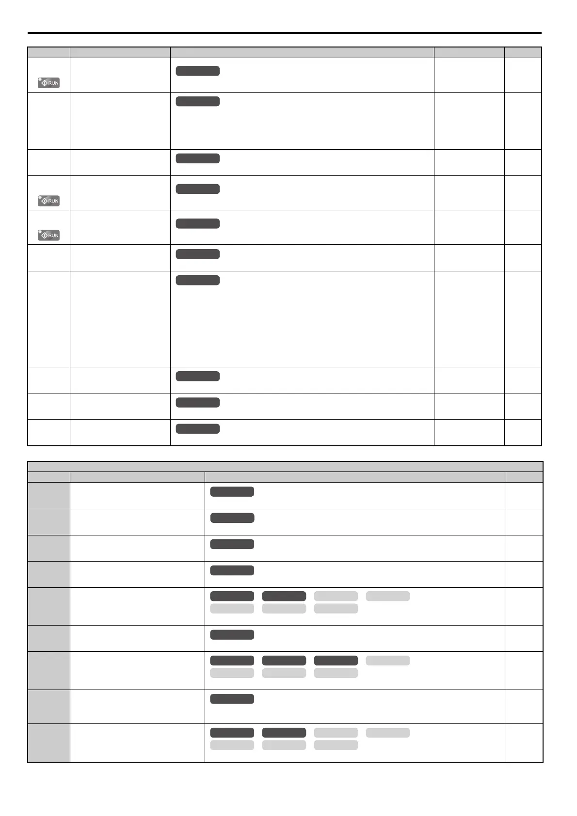
H3-08
(416H)
Terminal A3 Bias Setting
Sets the level of the input value selected in H3-06 when 0 V is input at terminal A3.
Default: 0.0%
Min: -999.9%
Max: 999.9%
258
H3-09
(417H)
Terminal A2 Signal Level
Selection
0: 0 to 10 V
1: -10 to 10 V
2: 4 to 20 mA
3: 0 to 20 mA
Note: Use DIP switch S1 to set input terminal A2 for a current or a voltage input signal.
Default: 2
Min: 0
Max: 3
258
H3-10
(418H)
Terminal A2 Function Selection
Sets the function of terminal A2.
Default: 0
Min: 0
Max: 32
259
H3-11
(419H)
Terminal A2 Gain Setting
Sets the level of the input value selected in H3-10 when 10 V (20 mA) is input at terminal A2.
Default: 100.0%
Min: -999.9%
Max: 999.9%
259
H3-12
(41AH)
Terminal A2 Bias Setting
Sets the level of the input value selected in H3-10 when 0 V (0 or 4 mA) is input at terminal A2.
Default: 0.0%
Min: -999.9%
Max: 999.9%
259
H3-13
(41BH)
Analog Input Filter Time Constant
Sets a primary delay filter time constant for terminals A1, A2, and A3. Used for noise filtering.
Default: 0.03 s
Min: 0.00 s
Max: 2.00 s
259
H3-14
(41CH)
Analog Input Terminal Enable
Selection
Determines which of the analog input terminals will be enabled or disabled when a digital input
programmed for “Analog input enable” (H1- = C) is activated. The terminals other than the
one set as the target are not influenced by input signals.
1: Terminal A1 only
2: Terminal A2 only
3: Terminals A1 and A2 only
4: Terminal A3 only
5: Terminals A1 and A3
6: Terminals A2 and A3
7: All terminals enabled
Default: 7
Min: 1
Max: 7
259
H3-16
(2F0H)
Terminal A1 Offset
Adds an offset when the analog signal to terminal A1 is at 0 V.
Default: 0
Min: -500
Max: 500
260
H3-17
(2F1H)
Terminal A2 Offset
Adds an offset when the analog signal to terminal A2 is at 0 V.
Default: 0
Min: -500
Max: 500
260
H3-18
(2F2H)
Terminal A3 Offset
Adds an offset when the analog signal to terminal A3 is at 0 V.
Default
: 0
Min: -500
Max: 500
260
H3 Multi-Function Analog Input Settings
Setting Function Description (For when output is 100%) Page
0 Frequency Bias
10 V = E1-04 (maximum output frequency)
260
1 Frequency Gain
0 to 10 V signal allows a setting of 0 to 100%. -10 to 0 V signal allows a setting of -100 to 0%.
260
2 Auxiliary Frequency Reference 1
10 V = E1-04 (maximum output frequency)
260
3 Auxiliary Frequency Reference 2
10 V = E1-04 (maximum output frequency)
260
4 Output Voltage Bias
10 V = E1-05 (motor rated voltage)
260
5 Accel/Decel Time Gain
10 V = 100%
261
6 DC Injection Braking Current
10 V = Drive rated current
261
7 Overtorque/Undertorque Detection Level
10 V = Drive rated current (V/f, V/fw/PG)
10 V = Motor rated torque (OLV, CLV, OLV/PM, AOLV/PM, CLV/PM)
261
8 Stall Prevention Level During Run
10 V = Drive rated current
261
No.(Addr.) Name Description Setting Page
All Modes
All Modes
All Modes
All Modes
All Modes
All Modes
All Modes
All Modes
All Modes
All Modes
All Modes
All Modes
OLV/PM AOLV/PM
CLV
V/f w/PG
CLV/PM
V/f OLV
All Modes
OLV/PM AOLV/PM
CLV
V/f w/PG
CLV/PM
V/f OLV
All Modes
OLV/PM AOLV/PM
CLV
V/f w/PG
CLV/PM
V/f OLV
 Loading...


