B.3 Parameter Table
YASKAWA ELECTRIC SIEP C710616 27G YASKAWA AC Drive A1000 Technical Manual 511
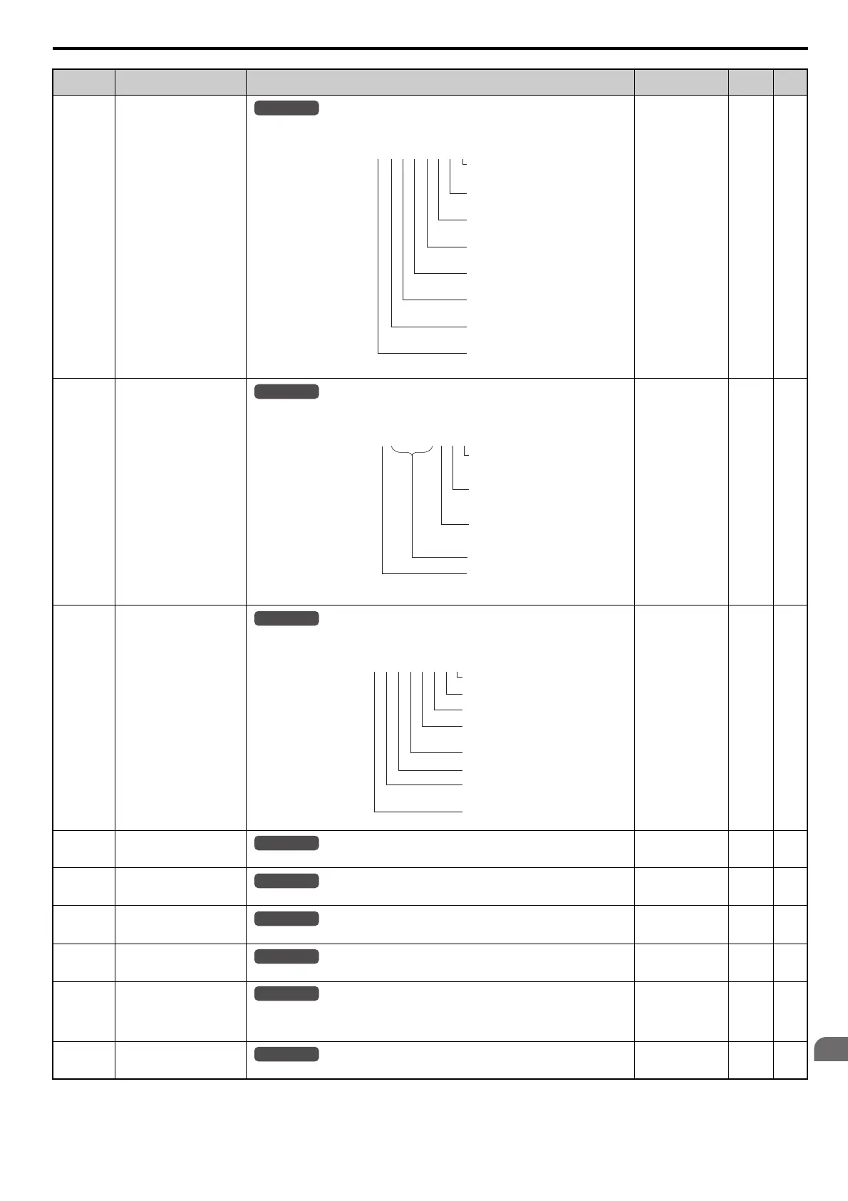
U1-10
(49H)
Input Terminal Status
Displays the input terminal status.
No signal output
available
––
U1-11
(4AH)
Output Terminal Status
Displays the output terminal status.
No signal output
available
––
U1-12
(4BH)
Drive Status
Displays the drive operation status.
No signal output
available
––
U1-13
(4EH)
Terminal A1 Input Level
Displays the signal level to analog input terminal A1.
10 V: 100%
(-10 to +10 V)
0.1% –
U1-14
(4FH)
Terminal A2 Input Level
Displays the signal level to analog input terminal A2.
10 V: 100%
(-10 to +10 V)
0.1% –
U1-15
(50H)
Terminal A3 Input Level
Displays the signal level to analog input terminal A3.
10 V: 100%
(-10 to +10 V)
0.1% –
U1-16
(53H)
Output Frequency after Soft
Starter
Displays output frequency with ramp time and S-curves. Units determined by o1-03.
10 V: Max frequency
(-10 to +10 V)
0.01 Hz –
U1-17
(58H)
DI-A3 Input Status
Displays the reference value input from the DI-A3 option card.
Display will appear in hexadecimal as determined by the digital card input selection in F3-01.
3FFFF: Set (1 bit) + sign (1 bit) + 16 bit
No signal output
available
––
U1-18
(61H)
oPE Fault Parameter
Displays the parameter number that caused the oPE02 or oPE08 (Operation error).
No signal output
available
––
No. (Addr.) Name Description
Analog Output
Level
Unit Page
All Modes
U1
-
10=
00000000
Digital input 1
(terminal S1 enabled)
Digital input 2
(terminal S2 enabled)
Digital input 3
(terminal S3 enabled)
Digital input 4
(terminal S4 enabled)
Digital input 5
(terminal S5 enabled)
Digital input 6
(terminal S6 enabled)
Digital input 7
(terminal S7 enabled)
Digital input 8
(terminal S8 enabled)
1
1
1
1
1
1
1
1
U1
-
11=
00000000
Multi-Function
Digital Output
(terminal M1-M2)
Digital Output
(terminal M3-M4)
Digital Output
(terminal M5-M6)
Multi-Function
Multi-Function
Not Used
Fault Relay Output
(terminal MA-MC closed
MA/MB-MC open)
1
1
1
1
All Modes
U1
-
12=
00000000
During run
During zero-speed
During REV
During fault reset
signal input
During speed agree
Drive ready
During alarm
detection
During fault detection
1
1
1
1
1
1
1
1
All Modes
All Modes
All Modes
All Modes
All Modes
All Modes