B.3 Parameter Table
512 YASKAWA ELECTRIC SIEP C710616 27G YASKAWA AC Drive A1000 Technical Manual
U2: Fault Trace
U1-19
(66H)
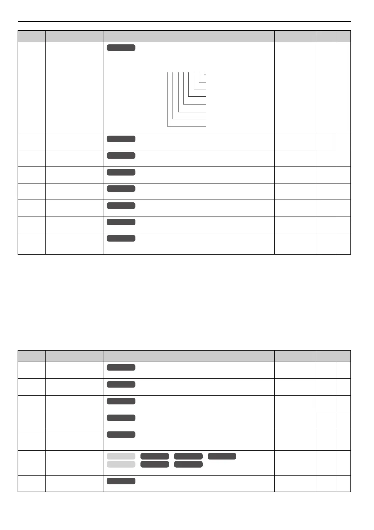
MEMOBUS/Modbus Error
Code
Displays the contents of a MEMOBUS/Modbus error.
No signal output
available
––
U1-21
(77H)
AI-A3 Terminal V1 Input
Voltage Monitor
Displays the input voltage to terminal V1 on analog input card AI-A3.
10 V: 100%
(-10 to +10 V)
0.1% –
U1-22
(72AH)
AI-A3 Terminal V2 Input
Voltage Monitor
Displays the input voltage to terminal V2 on analog input card AI-A3.
10 V: 100%
(-10 to +10 V)
0.1% –
U1-23
(72BH)
AI-A3 Terminal V3 Input
Voltage Monitor
Displays the input voltage to terminal V3 on analog input card AI-A3.
10 V: 100%
(-10 to +10 V)
0.1% –
U1-24
(7DH)
Input Pulse Monitor
Displays the frequency to pulse train input terminal RP.
Determined by H6-02 1 Hz –
U1-25
(4DH)
Software Number (Flash)
FLASH ID
No signal output
available
––
U1-26
(5BH)
Software No. (ROM)
ROM ID
No signal output
available
––
U1-29
(7AAH)
Software No. (PWM)
PWM ID
Note: This parameter is displayed in models CIMR-A4A0930 and 4A1200.
No signal output
available
––
<18> Values shown here are for 200 V class drives. Double the value when using a 400 V class drive.
<19> Display is in the following units.
CIMR-A2A0004 to 2A0040, CIMR-A4A0002 to 4A0023: 0.01 A units
CIMR-A2A0056 to 2A0312, CIMR-A4A0031 to 4A0675: 0.1 A units
CIMR-A4A0930 to 4A1200: 1 A units
<22> The display resolution depends on the rated output power of the drive after the Drive Duty has been set in parameter C6-01. Drives with a
maximum output up to 11 kW will display this value in units of 0.01 kW (two decimal places). Drives with a maximum output greater than 11
kW will display this value in units of 0.1 kW (one decimal place). Refer to Model Number and Nameplate Check on page 32 for details.
<23> When checking the values of U1-03, U2-05 and U4-13 with the digital operator they are displayed in units of amperes, but when they are
checked using MEMOBUS/Modbus communications, the monitor value in MEMOBUS/Modbus communications is: displayed numeric value
/ 8192 drive’ rated current (A), from the condition “8192 (maximum value) = drive’ rated current (A)”
<60> In V/f and V/f w/PG control mode, 10 V = drive capacity (kW). In OLV, CLV, OLV/PM, AOLV/PM, or CLV/PM control mode, 10 V = motor
rated power (E2-11) (kW).
No. (Addr.) Name Description
Analog Output
Level
Unit Page
U2-01
(80H)
Current Fault
Displays the current fault.
No signal output
available
––
U2-02
(81H)
Previous Fault
Displays the previous fault.
No signal output
available
––
U2-03
(82H)
Frequency Reference at
Previous Fault
Displays the frequency reference at the previous fault.
No signal output
available
0.01 Hz –
U2-04
(83H)
Output Frequency at Previous
Fault
Displays the output frequency at the previous fault.
No signal output
available
0.01 Hz –
U2-05
(84H)
Output Current at Previous
Fault
Displays the output current at the previous fault.
Note: The unit is expressed in 1 A for models CIMR-A4A0930 and 4A1200.
No signal output
available
<19> <23> –
U2-06
(85H)
Motor Speed at Previous Fault
Displays the motor speed at the previous fault.
No signal output
available
0.01 Hz –
U2-07
(86H)
Output Voltage at Previous
Fault
Displays the output voltage at the previous fault.
No signal output
available
0.1 Vac –
No. (Addr.) Name Description
Analog Output
Level
Unit Page
U1
-
19=
00000000
CRC Error
Data Length Error
Not Used
Parity Error
Overrun Error
Framing Error
Timed Out
Not Used
1
1
0
1
1
1
1
0
All Modes
All Modes
All Modes
All Modes
All Modes
All Modes
All Modes
All Modes
All Modes
OLV/PM AOLV/PM
CLV
V/f w/PG
CLV/PM
V/f OLV
All Modes