B.3 Parameter Table
YASKAWA ELECTRIC SIEP C710616 27G YASKAWA AC Drive A1000 Technical Manual 515
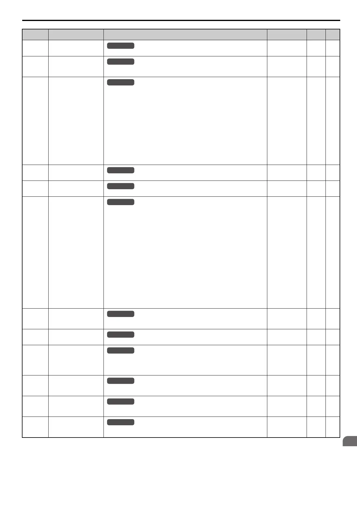
U4-14
(7D0H)
Peak Hold Output Frequency
Displays the output frequency when the current value shown in U4-13 occurred.
No signal output
available
0.01 Hz –
U4-16
(7D8H)
Motor Overload Estimate
(oL1)
Shows the value of the motor overload detection accumulator. 100% is equal to the oL1
detection level.
10 V: 100% 0.1% –
U4-18
(7DAH)
Frequency Reference Source
Selection
Displays the source for the frequency reference as XY-nn.
X: indicates which reference is used:
1 = Reference 1 (b1-01)
2 = Reference 2 (b1-15)
Y-nn: indicates the reference source
0-01 = Digital operator
1-00 = Analog
1-01 = Analog (terminal A1)
1-02 = Analog (terminal A2)
1-03 = Analog (terminal A3)
2-02 to 17 = Multi-step speed (d1-02 to 17)
3-01 = MEMOBUS/Modbus communications
4-01 = Communication option card
5-01 = Pulse input
7-01 = DWEZ
9-01 = Up/Down Command
No signal output
available
––
U4-19
(7DBH)
Frequency Reference from
MEMOBUS/Modbus Comm.
Displays the frequency reference provided by MEMOBUS/Modbus (decimal).
No signal output
available
0.01% –
U4-20
(7DCH)
Option Frequency Reference
Displays the frequency reference input by an option card (decimal).
No signal output
available
––
U4-21
(7DDH)
Run Command Source
Selection
Displays the source for the Run command as XY-nn.
X: Indicates which Run source is used:
1 = Reference 1 (b1-02)
2 = Reference 2 (b1-16)
Y: Input power supply data
0 = Digital operator
1 = External terminals
3 = MEMOBUS/Modbus communications
4 = Communication option card
7 = DWEZ
nn: Run command limit status data
00: No limit status.
01: Run command was left on when stopped in the PRG mode
02: Run command was left on when switching from LOCAL to REMOTE operation
03: Waiting for soft charge bypass contactor after power up (Uv or Uv1 flashes after 10 s)
04: Waiting for “Run command prohibited” time period to end
05: Fast Stop (digital input, digital operator)
06: b1-17 (Run command given at power-up)
07: During baseblock while coast to stop with timer
08: Frequency reference is below minimal reference during baseblock
09: Waiting for Enter command
No signal output
available
––
U4-22
(7DEH)
MEMOBUS/Modbus
Communications Reference
Displays the drive control data set by MEMOBUS/Modbus communications register no. 0001H
as a four-digit hexadecimal number.
No signal output
available
––
U4-23
(7DFH)
Communication Option Card
Reference
Displays drive control data set by an option card as a four-digit hexadecimal number.
No signal output
available
––
U4-32
(7FBH)
Option Card Reference
Displays the motor temperature (NTC).
U4-32 will display 20C
when a multi-function analog input is not set for motor thermistor
input (H1- = 17H).
Note: This parameter is displayed in models CIMR-A4A0930 and 4A1200.
200C1C–
U4-37
(1044H)
oH Alarm Location Monitor
Displays the module where the oH alarm occurred as a binary number.
Note: This parameter is displayed in models CIMR-A4A0930 and 4A1200.
No signal output
available
––
U4-38
(1045H)
FAn Alarm Location Monitor
Displays the module where the FAn alarm occurred as a binary number.
Note: This parameter is displayed in models CIMR-A4A0930 and 4A1200.
No signal output
available
––
U4-39
(1046H)
voF Alarm Location Monitor
Displays the module where the voF alarm occurred as a binary number.
Note: This parameter is displayed in models CIMR-A4A0930 and 4A1200.
No signal output
available
––
<19> Display is in the following units.
CIMR-A2A0004 to 2A0040, CIMR-A4A0002 to 4A0023: 0.01 A units
CIMR-A2A0056 to 2A0312, CIMR-A4A0031 to 4A0675: 0.1 A units
CIMR-A4A0930 to 4A1200: 1 A units
No. (Addr.) Name Description
Analog Output
Level
Unit Page
All Modes
All Modes
All Modes
All Modes
All Modes
All Modes
All Modes
All Modes
All Modes
All Modes
All Modes
All Modes