B.3 Parameter Table
516 YASKAWA ELECTRIC SIEP C710616 27G YASKAWA AC Drive A1000 Technical Manual
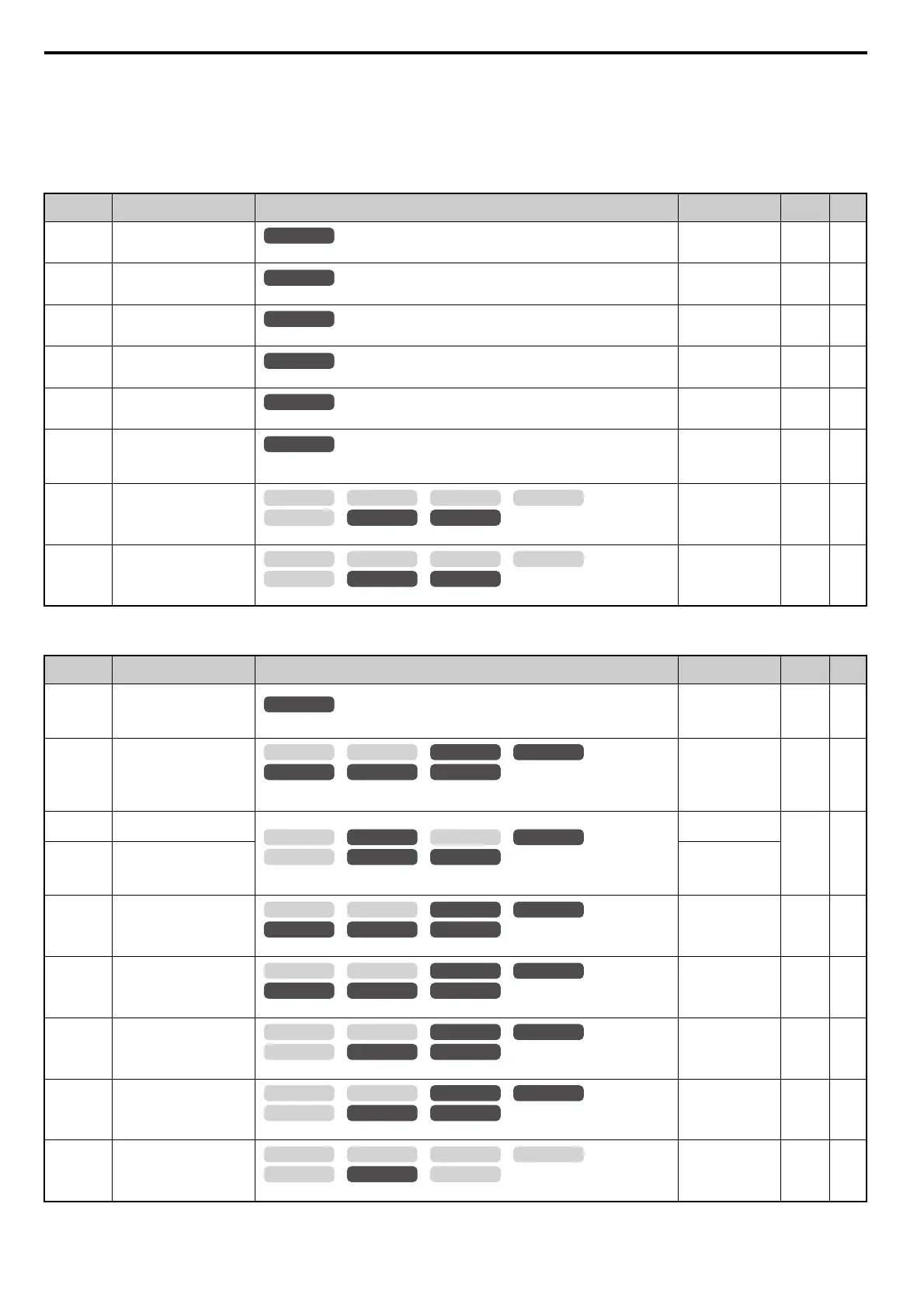
U5: PID Monitors
U6: Control Monitors
<23> When checking the values of U1-03, U2-05 and U4-13 with the digital operator they are displayed in units of amperes, but when they are
checked using MEMOBUS/Modbus communications, the monitor value in MEMOBUS/Modbus communications is: displayed numeric value
/ 8192 drive’ rated current (A), from the condition “8192 (maximum value) = drive’ rated current (A)”
<26> The MEMOBUS/Modbus communications data is in 10 h units. If data in 1 h units are also required, refer to register number 0099H.
<58> The MEMOBUS/Modbus communications data is in 10 h units. If data in 1 h units are also required, refer to register number 009BH.
No. (Addr.) Name Description
Analog Output
Level
Unit Page
U5-01
(57H)
PID Feedback
Displays the PID feedback value.
10 V: 100%
(-10 to +10 V)
0.01% –
U5-02
(63H)
PID Input
Displays the amount of PID input (deviation between PID setpoint and feedback).
10 V: 100%
(-10 to +10 V)
0.01% –
U5-03
(64H)
PID Output
Displays PID control output.
10 V: 100%
(-10 to +10 V)
0.01% –
U5-04
(65H)
PID Setpoint
Displays the PID setpoint.
10 V: 100%
(-10 to +10 V)
0.01% –
U5-05
(7D2H)
PID Differential Feedback
Displays the 2nd PID feedback value if differential feedback is used (H3- = 16).
10 V: 100%
(-10 to +10 V)
0.01% –
U5-06
(7D3H)
PID Adjusted Feedback
Displays the difference of both feedback values if differential feedback is used (U5-01) -
(U5-05). If differential feedback is not used, then U5-01 and U5-06 will be the same.
10 V: 100%
(-10 to +10 V)
0.01% –
U5-21
(872H)
Automatically Calculated
Energy Saving Coefficient Ki
Va lu e
Displays the energy saving coefficient Ki value.
No signal output
available
0.01 –
U5-22
(873H)
Automatically Calculated
Energy Saving Coefficient Kt
Va lu e
Displays the energy saving coefficient Kt value.
No signal output
available
0.01 –
No. (Addr.) Name Description
Analog Output
Level
Unit Page
U6-01
(51H)
Motor Secondary Current (Iq)
Displays the value of the motor secondary current (Iq). Motor rated secondary current is 100%.
10 V: Motor
secondary rated
current
(-10 to +10 V)
0.1% –
U6-02
(52H)
Motor Excitation Current (Id)
Displays the value calculated for the motor excitation current (Id). Motor rated secondary
current is 100%.
10 V: Motor
secondary rated
current
(-10 to +10 V)
0.1% –
U6-03
(54H)
ASR Input
Displays the input and output values when using ASR control.
10 V: Max frequency
(-10 to +10 V)
0.01% –
U6-04
(55H)
ASR Output
10 V: Motor
secondary rated
current
(-10 to +10 V)
U6-05
(59H)
Output Voltage Reference (Vq)
Output voltage reference (Vq) for the q-axis.
10 V: 200 Vrms
<18>
(-10 to +10 V)
0.1 Vac –
U6-06
(5AH)
Output Voltage Reference (Vd)
Output voltage reference (Vd) for the d-axis.
10 V: 200 Vrms
<18>
(-10 to +10 V)
0.1 Vac –
U6-07
(5FH)
q-Axis ACR Output
Displays the output value for current control relative to motor secondary current (q-axis).
10 V: 200 Vrms
<18>
(-10 to +10 V)
0.1% –
U6-08
(60H)
d-Axis ACR Output
Displays the output value for current control relative to motor secondary current (d-axis).
10 V: 200 Vrms
<18>
(-10 to +10 V)
0.1% –
U6-09
(7C0H)
Advance Phase Compensation
()
Displays the degree of forward phase correction after calculating the deviation of cmp.
10 V: 180 deg
-10 V: -180 deg
(-10 to +10 V)
0.1 deg –
All Modes
All Modes
All Modes
All Modes
All Modes
All Modes
OLV/PM AOLV/PM
CLV
V/f w/PG
CLV/PM
V/f OLV
OLV/PM AOLV/PM
CLV
V/f w/PG
CLV/PM
V/f OLV
All Modes
OLV/PM AOLV/PM
CLV
V/f w/PG
CLV/PM
V/f OLV
OLV/PM AOLV/PM
CLV
V/f w/PG
CLV/PM
V/f OLV
OLV/PM AOLV/PM
CLV
V/f w/PG
CLV/PM
V/f OLV
OLV/PM AOLV/PM
CLV
V/f w/PG
CLV/PM
V/f OLV
OLV/PM AOLV/PM
CLV
V/f w/PG
CLV/PM
V/f OLV
OLV/PM AOLV/PM
CLV
V/f w/PG
CLV/PM
V/f OLV
OLV/PM AOLV/PM
CLV
V/f w/PG
CLV/PM
V/f OLV