D.4 Safe Disable Input Function
YASKAWA ELECTRIC SIEP C710616 27G YASKAWA AC Drive A1000 Technical Manual 601
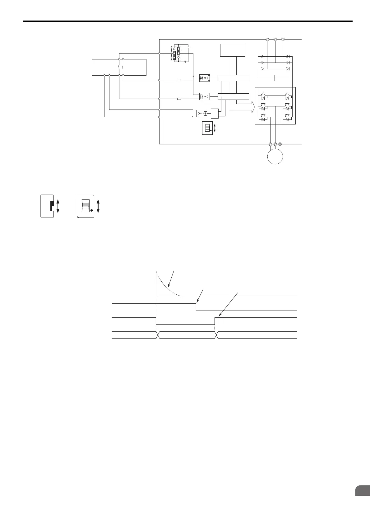
Figure D.12
Figure D.12 Safe Disable Function Wiring Example (Source Mode)
Disabling and Enabling the Drive Output (“Safe Torque Off”)
Figure D.13 illustrates the Safe Disable input operation.
Figure D.13
Figure D.13 Safe Disable Operation
Entering the “Safe Torque Off” State
Whenever either one Safe Disable input or both inputs open, the motor torque is shut off by switching off the drive
output. If the motor was running before the Safe Disable inputs opened, then the motor will coast to stop, regardless of
the stopping method set in parameter b1-03.
Notice that the “Safe Torque Off” state can only be achiev
ed using the Safe Disable function. Removing the Run
command stops the drive and shuts the output off (baseblock), but does not create a “Safe Torque Off” status.
Note: To avoid an uncontrolled stop during normal operation, make sure that the Safe Disable inputs are opened first when the motor
has completely stopped.
<1> Available slide switch S6 is models ETC740310 and ETC740311.
24 Vdc
Safety
Outputs
Power Module
PN
Motor
Gate Block 2
Gate Block 1
Control
Circuit
Main Power
H1
H2
HC
Drive
Slide Switch S6
Jumper S3
Setting:
SOURCE
>=1
DM+
DM-
Feedback
Safety Relay or PLC
with safety functionality
N.C.
N.O.
<1>
N.C.
N.O.
N.C.
ETC740311ETC740310
N.O.
H1, H2 Input
Drive Output
ON (Safe Disable off)
Normal operation
OFF (Safe Disable activated)
Safe Torque-Off
Run Command
Run Stop
Baseblock (Not Safe!)
Output
Frequency
Motor coasts
to stop
Run Command must be
released to deactivate
Safe Disable
Drive is ready for
operation