3.2 Standard Connection Diagram
YASKAWA ELECTRIC SIEP C710616 27G YASKAWA AC Drive A1000 Technical Manual 61
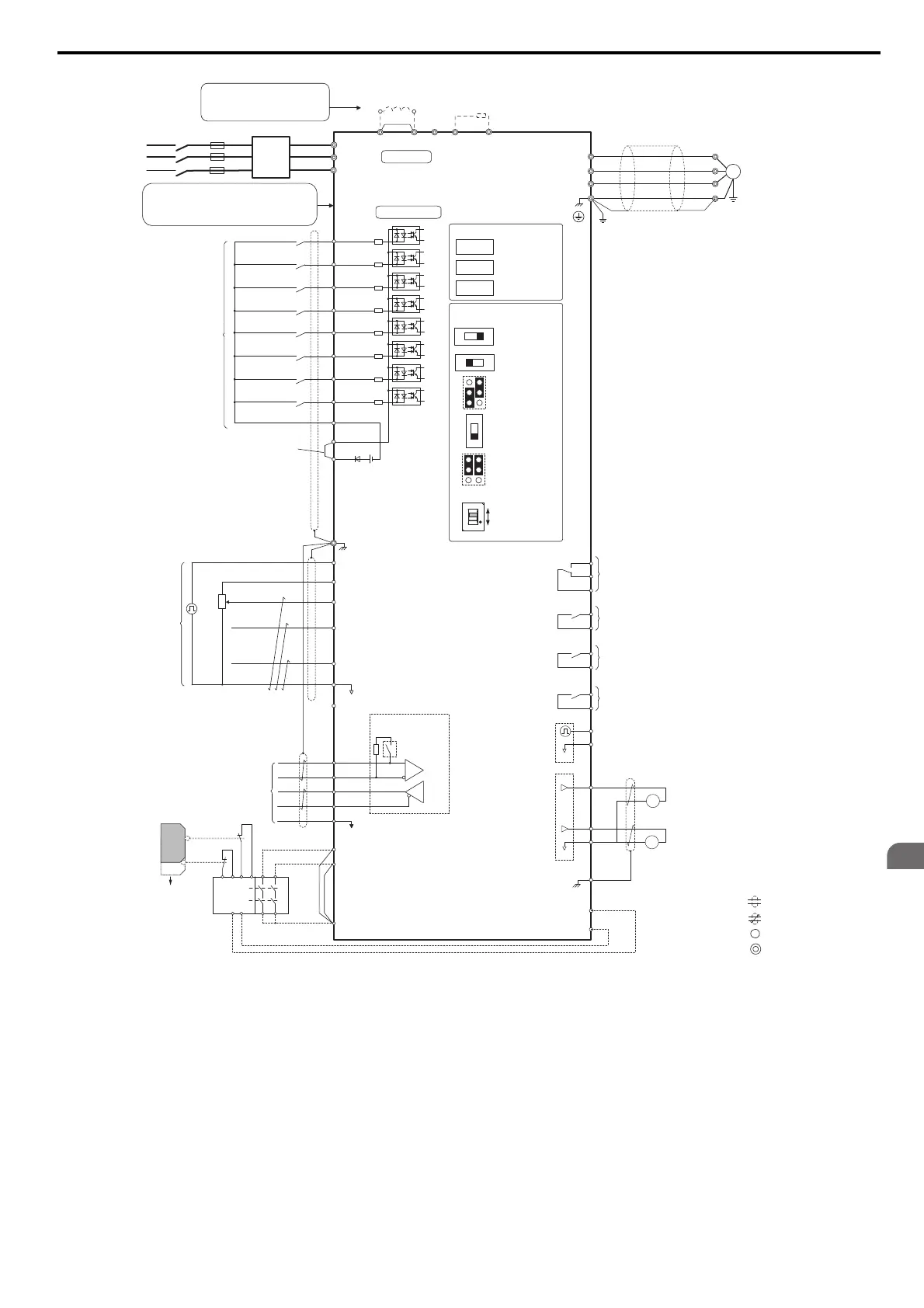
Figure 3.2
Figure 3.1 Drive Standard Connection Diagram (example: CIMR-A2A0040)
<1> Remove the jumper when installing a DC reactor. Models CIMR-A2A0110 through 2A0415 and 4A0058 through 4A1200 come with a
built-in DC reactor.
<2> When installing a dynamic braking option, a thermal relay sequence should also be set up to shut off power to the drive in case overheat
occurs.
<3> The drive’s protection function for the internal braking transistor needs to be disabled (L8-55 = 0) if using a regen unit such as a regen
converter or some type of dynamic braking options (and therefore not the internal braking transistor). If left enabled, a braking resistor fault
(rF) may result. Make sure Stall Prevention is disabled (L3-04 = 0) whenever using a regenerative converter, a regenerative unit or a dynamic
braking option. If left enabled, the drive may not stop within the specified deceleration time.
<4> Supplying power to the control circuit separately from the main circuit requires a 24 V power supply (option).
<5> This figure shows an example of a sequence input to S1 through S8 using a non-powered relay or an NPN transistor. Install the wire link
between terminals SC-SP for Sink mode and SC-SN for Source mode. Leave it out for external power supply. Never short terminals SP and
SN as doing so will damage the drive. (see Sinking/Sourcing Mode for Digital Inputs on page 88)
<6> The maximum current supplied by this voltage source is 150 mA if no digital input option card DI-A3 is used.
N.C.
N.O.
+
−
+
+
++
M
U/T
1
V/T2
W/T
U
V
W
3
Ground
Terminals -, +1, +2, B1, B2 are
for connection options. Never
connect power supply lines to
these terminals
DC reactor
(option)
UX
+
−
+
+
++
+
−
UX
S
1
S2
S3
S4
S5
S6
S7
MP
DM
DM
RP
A
1
A2
A3
0
V
AC
R
R
S
S
IG
H
1
H2
HC
Drive
B112
B2
2
kΩ
S8
SC
0 V
0 V
AC
FM
AM
AC
E (G)
S
1
S2
<1>
<2><3>
<12>
<8>
<13>
<14>
<14>
<11>
<8>
<9>
<5>
<4>
−
+24 V
+V
MA
M
1
M2
MB
MC
Jumper
Braking resistor
(option)
Forward Run / Stop
Reverse Run / Stop
External fault
Fault reset
Multi-speed step 1
Multi-speed step 2
External Baseblock
Jog speed
Multi-function
digtial inputs
(default setting)
Sink / Source mode
selection wire link
(default: Sink)
CN5-C
CN5-B
CN5-A
Option card connectors
Pulse Train Input (max 32 kHz)
Shield ground terminal
Multi-function
analog/ pulse
train inputs
Power supply +10.5 Vdc, max. 20 mA
Analog Input 1 (Frequency Reference Bias)
-10 to +10 Vdc (20 k
Ω
)
Analog Input 2 (Frequency Reference Bias)
-10 to +10 Vdc (20 k
Ω
)
0 or 4 to 20 mA (250
Ω
)
Analog Input 3 / PTC Input (Aux. frequency
reference)
-10 to +10 Vdc (20 k
Ω
)
−V
Power supply, -10.5 Vdc, max. 20 mA
Safety
Switch
MEMOBUS/Modbus
comm. RS-422/RS-485
max. 115.2 kBps
Safe Disable inputs
Wire
jumper
Open
Safety relay /
controller
Termination resistor
(120
Ω
, 1/2 W)
DIP
Switch S2
Fault relay output
250 Vac, max. 1 A
30 Vdc, max 1 A
(min. 5 Vdc, 10 mA)
Multi-function relay output (During Run)
250 Vac, max. 1 A
30 Vdc, max 1 A
(min. 5 Vdc, 10 mA)
Multi-function pulse train output
(Output frequency)
0 to 32 kHz (2.2 k
Ω
)
Multi-function analog output 1
(Output frequency)
-10 to +10 Vdc (2mA) or 4 to 20 mA
Multi-function analog output 2
(Output current)
-10 to +10 Vdc (2mA) or 4 to 20 mA
EDM (Safety Electronic Device Monitor)
Main Circuit
Control Circuit
shielded line
twisted-pair shielded line
main circuit terminal
control circuit terminal
R/L1
S/L2
T/L3
Three-phase
power supply
200 to 400 V
50/60 Hz
R/L1
S/L2
T/L3
Main
Switch
Fuse
EMC
Filter
Motor
Shielded
Cable
M3
M4
Multi-function relay output (Zero Speed)
250 Vac, max. 1 A
30 Vdc, max 1 A
(min. 5 Vdc, 10 mA)
M5
M6
Multi-function relay output (Speed Agree 1)
250 Vac, max. 1 A
30 Vdc, max 1 A
(min. 5 Vdc, 10 mA)
SP
SN
<10>
AMFM
V
I
V
I
DIP Switch S1
A2 Volt/Curr. Sel
DIP Switch S4
A3 Analog/PTC
Input Sel
PTC
AI
Off
On
DIP Switch S2
Term. Res. On/Off
Jumper S3
H1, H2
Sink/Source Sel.
Jumper S5
AM/FM Volt./Curr.
Selection
Terminal board
jumpers and switches
FM
+
−
AM
<6>
<15>
<16>
Models CIMR-A4A0930 and 4A1200 are
compatible for operation with 12-phase rectification.
Slide Switch S6
DM+,DM-
N.C./N.O. Selection
<7>
Refer to 12-Phase Rectification on page 64.