11 Modification of System Configuration
DX100 11.2 Addition of Base and Station Axes
11-12
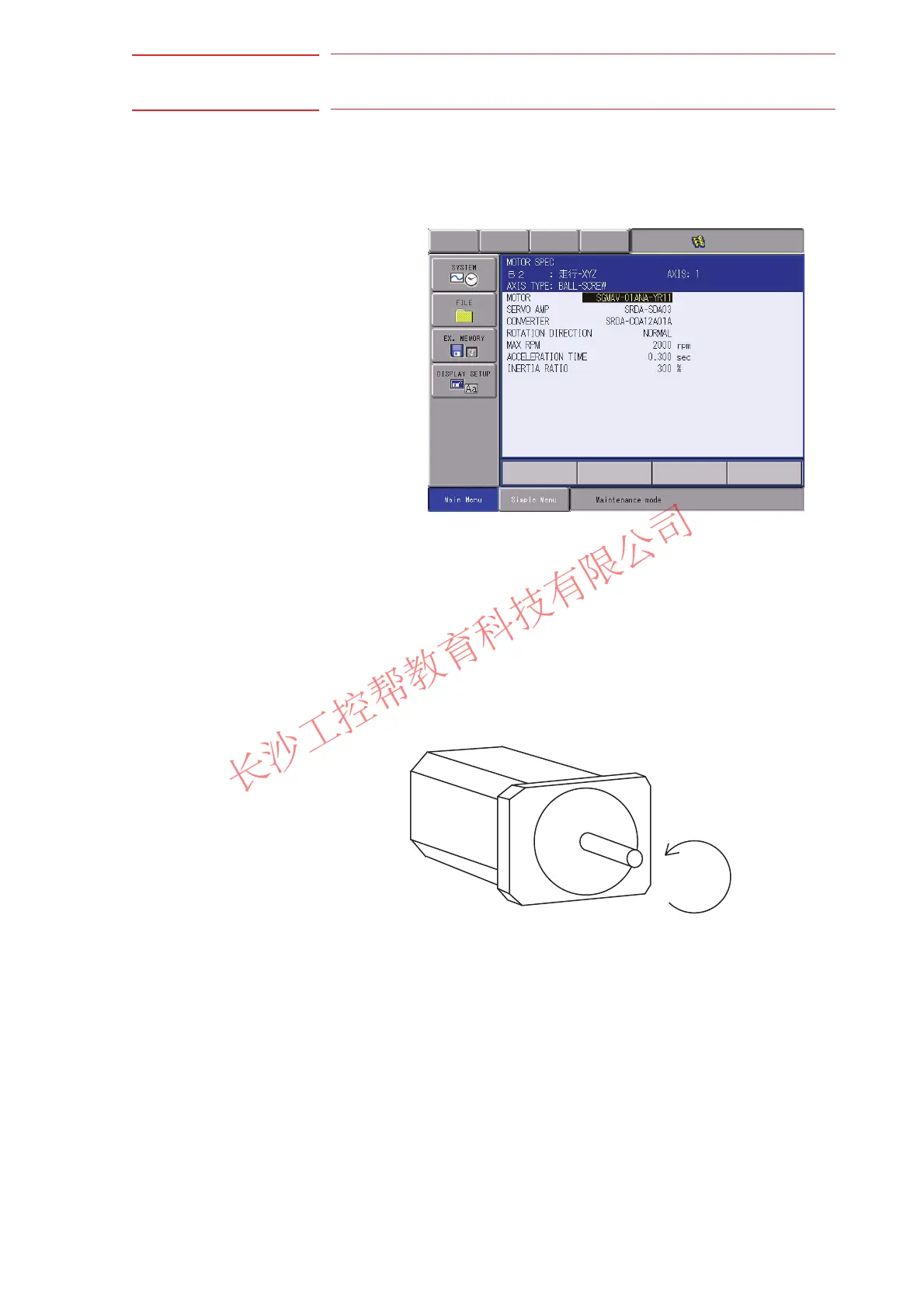
11.2.1.5 Motor Specification Setting
The motor data is specified in the MOTOR SPEC window.
1. Confirm specification of each axis in the MOTOR SPEC window.
– The motor specification of each axis is displayed.
2. Select the desired item.
– When a numerical value is selected, the number input buffer line
appears.
– When MOTOR (or SERVO AMP or CONVERTER) is selected, the
list window of MOTOR (SERVO AMP, or CONVERTER) appears.
– ROTATION DIRECTION: Set the rotation direction to which the
current position is increased. (The counterclockwise view from the
loaded side is the normal rotation.)
Fig. 11-1: AC Servo Motor
– MAX. RPM: Input maximum rotation speed of a motor. (Unit: rpm)
– ACCELARATION TIME: Input time between 0.01 and 1.00 to reach
maximum speed from stopping status at 100% JOINT speed.
(Unit: sec)
– INERTIA RATIO: The initial value is set at 300 in case of servo track;
0 in case of rotation axis.
However, if the following phenomenon occurs in motion, deal with
the followed procedure.
– <Phenomenon1>
During motion, the axis moves unsteady on advance direction.
Confirm the motion with increasing this ratio in each 100.
Normal direction

 Loading...


