8 System Setup
DX100 8.3 Tool Data Setting
8-24
8.3.2.3 Teaching of Calibration Point
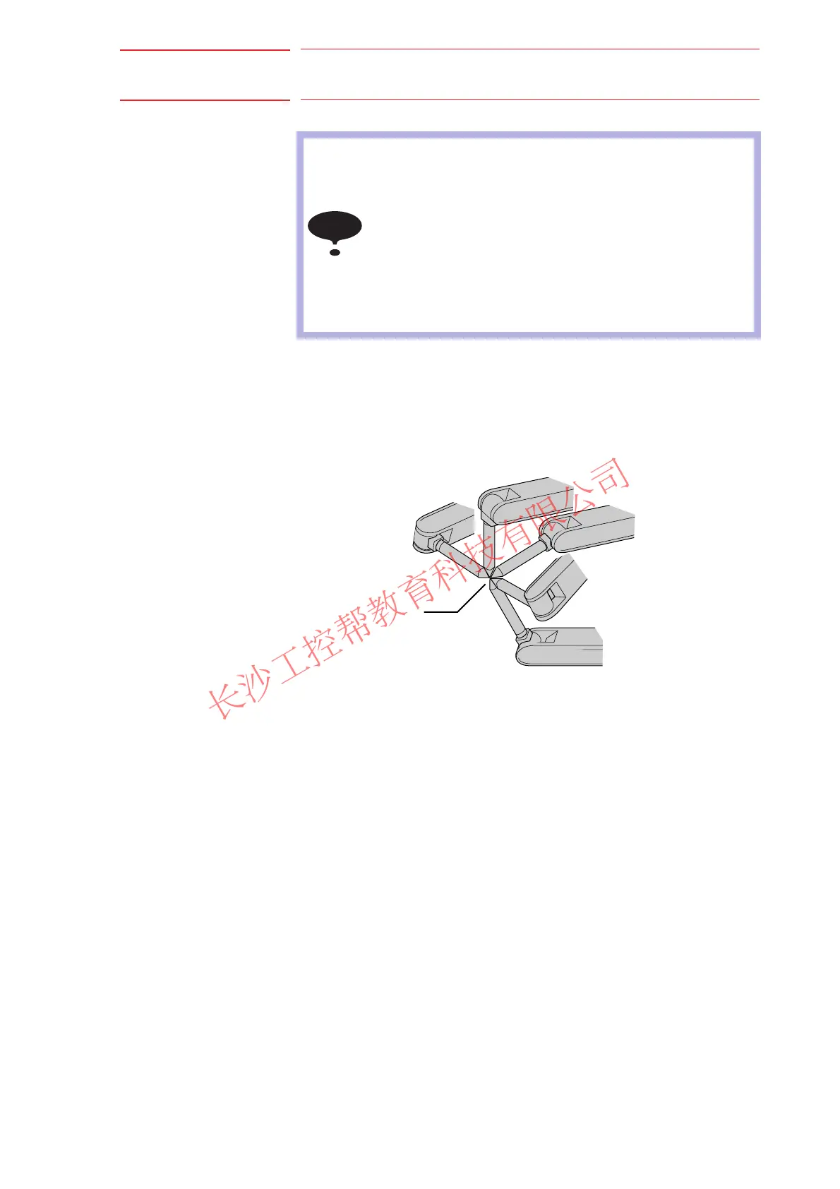
Teaching for defining coordinates
In order to calibrate coordinates, five different postures (TC1 to 5) must be
taught with the TCP as the reference point. The tool dimensions are
automatically calculated on the basis of these five points.
Each posture must be arbitrary. Accuracy may decrease when pose
setting is rotated in a constant direction
Teaching for defining posture
The calibration of tool posture data is performed with the first calibration
teaching point (TC1).
Teach TC1 with Z-axis of the desired tool coordinates downward vertically
to the ground. (the Z-axis of the tool coordinates is parallel to the Z-axis of
the base tool and points to the opposite direction.)
Tool posture data is automatically calcurated with this TC1 posture.
NOTE
• In case of S2C432=0 (only coordiantes is calibrated),
tool posture data is overwritten with 0.
(When the coordinates calculated from tool calibration is
registered in the tool file in which the tool posture data is
already registered, the tool posture data will be deleted.)
• In case of S2C432=1 (only posture is calibrated), the
coordinates are maintained.
• In case of S2C432=1, 5 teaching points need to be
registered though only the first point is used for
calculation.
TCP
TC1
TC2
TC3
TC4
TC5

 Loading...


