8 System Setup
DX100 8.3 Tool Data Setting
8-25
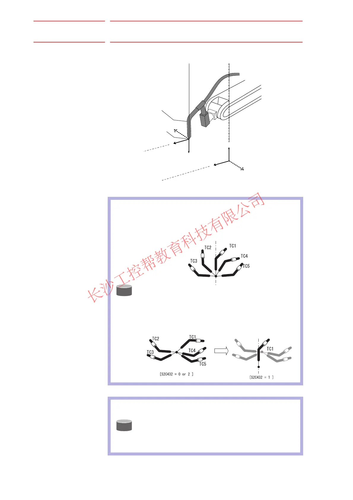
The X-axis of the tool coordinates is defined in the same direction as the
X-axis of the base coordinates.
SUPPLE
-MENT
In case of calibrating with S2C432=2, teach TC1 with Z-axis
of the desired tool coordinates downward vertically to the
ground. Then teach the other calibration teaching points
(TC2~TC5) with the all tool points meet at the TC1’s tool
point as shown in the figure below.
If teaching in one place as the figure above is impossible
due to the interferance of peripheral equipments and so on,
perform calibration of coordinates with S2C432=0 or 2, and
then change to S2C432=1, teach only TC1 in a different
position and register the tool posture data.
SUPPLE
-MENT
• There are 64 tool files numbered 0 to 63.
• In a basic system with one manipulator and one tool, the
tool file for tool No.0 is used.
• If there is more than one tool, for example when using a
multihand, use the tool numbers in the order of 0, 1, 2,
etc.
X
T
Y
T
Z
T
TCP
Tool
X
Y
Z
Tool
Coordinates
Base
Coordinates

 Loading...


