Triggering
6
7
8
9
10
11
12
13
14
15
16
17
18
Index
App
6-19
IM DLM6054-01EN
• Symbol
Symbols are a way of expressing bit sequences that include “don’t cares” (Xs). You can load
physical value/symbol definition files (with .sbl extensions) that you have edited using the Symbol
Editor tool.
• Logic (Logic)
When you set state conditions for groups of bits, the logic is fix
ed at AND. The result of
comparing the bit states to their specified state conditions is set to “met” when all the states
match.
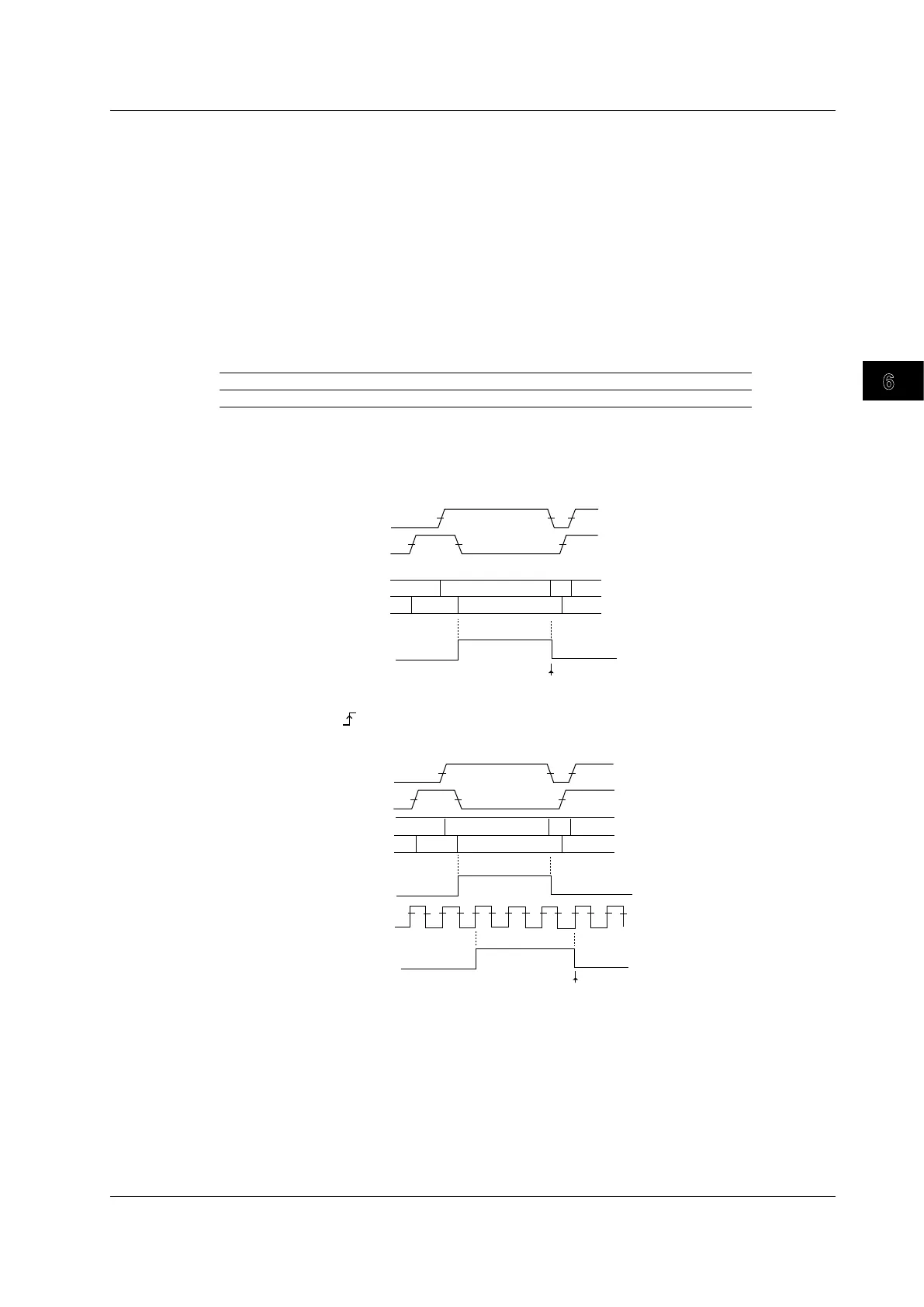
Trigger Condition (Polarity)
Select how the result of comparing the signal states to their state conditions must change for the
DLM6000 to trigger.
Enter The result must change from not met to met.
Exit The result must change from met to not met.
Examples
L
H
H
CH1
CH2
State: CH1 = H, CH2 = L, other channels = X, AND
Condition: Exit
CH1
CH2
H
H
L
L
L
Not met Not met
Met
Result of comparison with
the state conditions
Not met
Not met
Not met
Not met
Met
Met
CH1
CH2
Trigger
CH3
Clock source: CH3,
State: CH1 = H, CH2 = L, CH4 = X, AND
Condition: Exit
L
H
H
CH1
CH2
H
H
L
L
L
Results of comparisons
that have been sampled
using the clock
Result of comparison with
the state conditions
Trigger
6.6 Triggering on State Conditions
 Loading...


