2-3
IM DLM6054-01EN
Features
2
1
4
5
6
7
8
9
10
11
12
13
14
15
16
17
18
Index
App
section 5.1 for the procedure
If you only want to observe the amplitude of an AC signal, it is best to remove its DC component. On
the other hand, there are times when you want to check the ground level or observe the entire signal
including both the DC and AC components. In these kinds of situations, you should change the input
coupling setting. By changing the setting, you can choose how the vertical-axis (voltage-axis) control
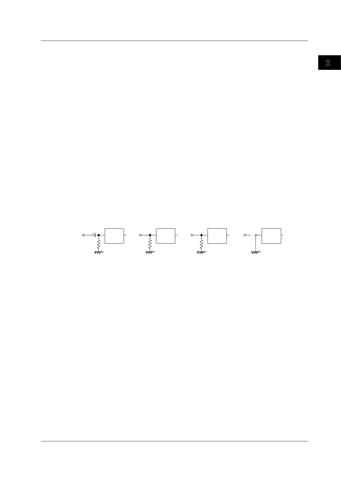
circuit is coupled to the analog signal. You can set the input coupling to one of the settings listed below.
AC1M
Ω
The analog signal is coupled to the attenuator of the vertical control circuit through a capacitor.
Use this setting when you want to observe only the amplitude of the AC signal without the DC
component.
DC1M
Ω
The analog signal is coupled directly to the attenuator of the vertical control circuit. Use this setting
when you want to observe the entire signal including both the DC and AC components.
DC50
Ω
The same as the DC1M
Ω
setting described above, except the input impedance is 50
Ω
. Remember
that the maximum input voltage is lower when you use this setting.
GND
The analog signal is coupled to the ground rather than to the attenuator of the vertical control circuit.
You can use this setting to check the ground level on the screen.
Vertical
control
circuit
Input
terminal
1 MΩ
Vertical
control
circuit
Input
terminal
Vertical
control
circuit
Input
terminal
50 Ω
Vertical
control
circuit
Input
terminal
1 MΩ
Probe Attenuation and
section 5.1 for the procedure
Normally, a probe is used to connect the circuit under measurement to a signal input terminal. Using a
probe has the following advantages.
• Does not disturb the voltage and current of the circuit being m
easured.
• Allows signals to be applied with no distortion.
• Expands the voltage range that the DL6000/DLM6000 can me
asure.
The DL6000/DLM6000 comes with 500 MHz passive probes. The probes attenuate the measured
voltage signal by a factor of 1/10. When you use a probe, to read the measurement voltage correctly,
you must set the attenuation on the DL6000/DLM6000 to match the probe attenuation. When you
connect the supplied 500 MHz passive probes (voltage probes) to the DL6000/DLM6000, the DL6000/
DLM6000 automatically recognizes the probes and sets the attenuation ratio to 10:1.
On the DL6000/DLM6000, you can choose one of the following attenuation ratios or current-to-voltage
conversion ratios.
Voltage Probe Attenuation Ratios
Auto, 1:1, 2:1, 5:1, 10:1, 20:1, 50:1, 100:1, 200:1, 500:1, and 1000:1
Current-to-Voltage Conversion Ratios
Auto, 1A:1V
, 10A:1V, and 100A:1V
When using a probe, set the DL6000/DLM6000 attenuation ratio or current-to-voltage conversion ratio
to match that of the probe.
For the procedure to connect the logic probe when measuring logic signals, see section 3.6.
2.2 Vertical (Analog Signal) and Horizontal Axes
 Loading...


