2-4
IM DLM6054-01EN
section 5.1 for the procedure
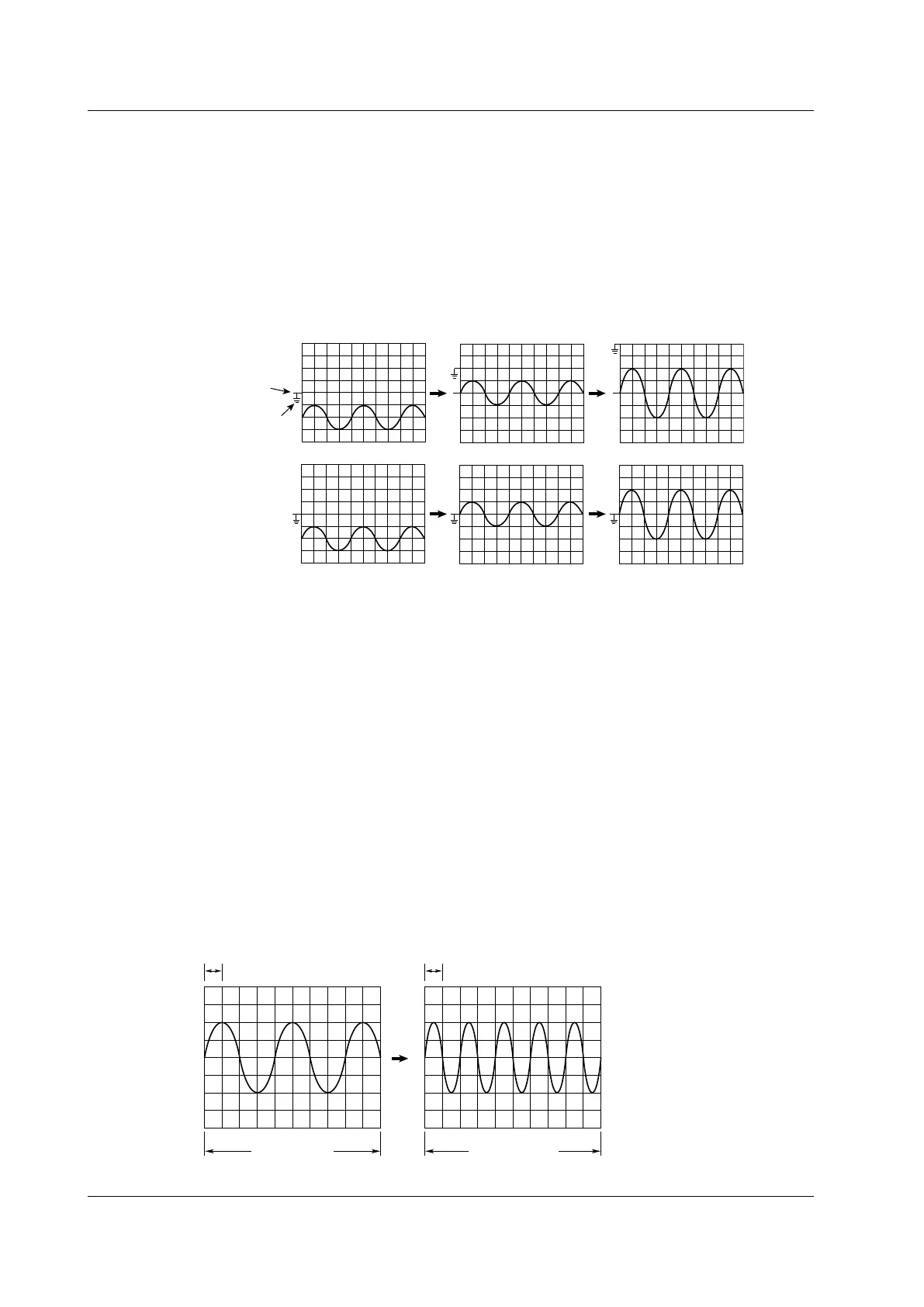
When observing an analog signal riding on top of a predetermined voltage, you can subtract the
predetermined offset voltage so that you can observe the changes in the signal by themselves with
higher vertical sensitivity.
Usually, the offset voltage does not affect cursor measurement values, automated measurements of
waveform parameters, or computed values. However, when you set Offset Cancel to ON (see section
5.1), cursor measurement values, automated measurements of waveform parameters, and computed
values are determined from values that have had the offset voltage subtracted from them.
Offset 0.00 V
Position 0.00 div
Offset –2.00 V
Position 0.00 div
Offset –2.00 V
Position 0.00 div
When Offset Cancel
is set to OFF
When Offset Cancel
is set to ON
Vertical position mark
Ground level mark
section 5.1 for the procedure
This feature inverts the waveform display around the vertical position. Because only the display is
inverted, the measured values do not change. Turning the inverted display on and off does not affect
the automated measurements of waveform parameters or calculations.
section 5.1 for the procedure
You can set bandwidth limits for analog signals by specifying cutoff frequencies for each channel. You
can view signals with the noise above a specified frequency removed. You can set the bandwidth to:
FULL, 200 MHz, 20 MHz, 8 MHz, 4 MHz, 2 MHz, 1 MHz, 500 kHz, 250 kHz, 125 kHz, 62.5 kHz, 32
kHz, 16 kHz, or 8 kHz.
Horizontal Axis ( section 5.3 for the procedure
section 5.8 for the procedure
The time scale is set as a length of time per grid division. You can set the scale to a value from 500
ps/division to 50 s/division. Because the horizontal display range is 10 divisions, the amount of time
displayed is equal to Time/div × 10.
1 div = 500 µs
10 div = 5 ms 10 div = 10 ms
1 div = 1 ms
2.2 Vertical (Analog Signal) and Horizontal Axes
 Loading...


