18-19
IM DLM6054-01EN
Specifications
3
2
1
4
5
6
7
8
9
10
11
12
13
14
15
16
17
18
Item Specifications
Emissions Compliant standard
EN61326-1 Class A
EN61326-2-1
EN55011 Class A Group1
C-Tick EN55011 Class A Group1
(Applicable to the DL6054, DL6104, DL6154, DLM6054, DLM6104, 701939, 701912, 01913,, DL6104, DL6154, DLM6054, DLM6104, 701939, 701912, 01913,DLM6054, DLM6104, 701939, 701912, 01913,
701914, 701923, 701974 with 701975, 701980
4
, 701981
4
, 701935
5
)
EN61000-3-2
EN61000-3-3
This is a class A instrument designed for an industrial environment. Operation of this
equipment in a residential area may cause radio interference, in which case users will be
required to correct the interference.
Cable conditions
Logic signal input port
4
701981 Attach a ferrite core (TDK: ZCAT2035-0930A, YOKOGAWA: A1190MN) to one end
(DL6000/DLM6000 end) of the logic probe cable.
701980 Attach ferrite cores (TDK: ZCAT2035-0930A, YOKOGAWA: A1190MN) to the both
end of logic probe cables.
External trigger input (TRIG IN) terminal
Use a BNC cable
6
and attach a ferrite core (TDK: ZCAT2035-0930A, YOKOGAWA:
A1190MN) on one end (DL6000/DLM6000 end).
Trigger output (TRIG OUT) terminal
Same as the external trigger input terminal above.
Video signal output (VIDEO OUT) terminal
Use a 15-pin D-Sub VGA shielded cable
6
and attach a ferrite core (TDK: ZCAT2035-0930A,
YOKOGAWA: A1190MN) on one end ((DL6000/DLM6000 end).
Probe power terminal
7
Attach a ferrite core (TDK: ZCAT1325-0530A, YOKOGAWA: A1181MN) to one end (DL6000/
DLM6000 end) of the power supply cable.
USB connector for connecting peripheral devices
Attach a ferrite core (TDK: ZCAT1325-0530A, YOKOGAWA: A1181MN) to one end (DL6000/
DLM6000 end) of the USB cable.
6
USB connector for connecting to a PC
Attach a ferrite core (TDK: ZCAT1325-0530A, YOKOGAWA: A1181MN) to one end (DL6000/
DLM6000 end) of the USB cable.
6
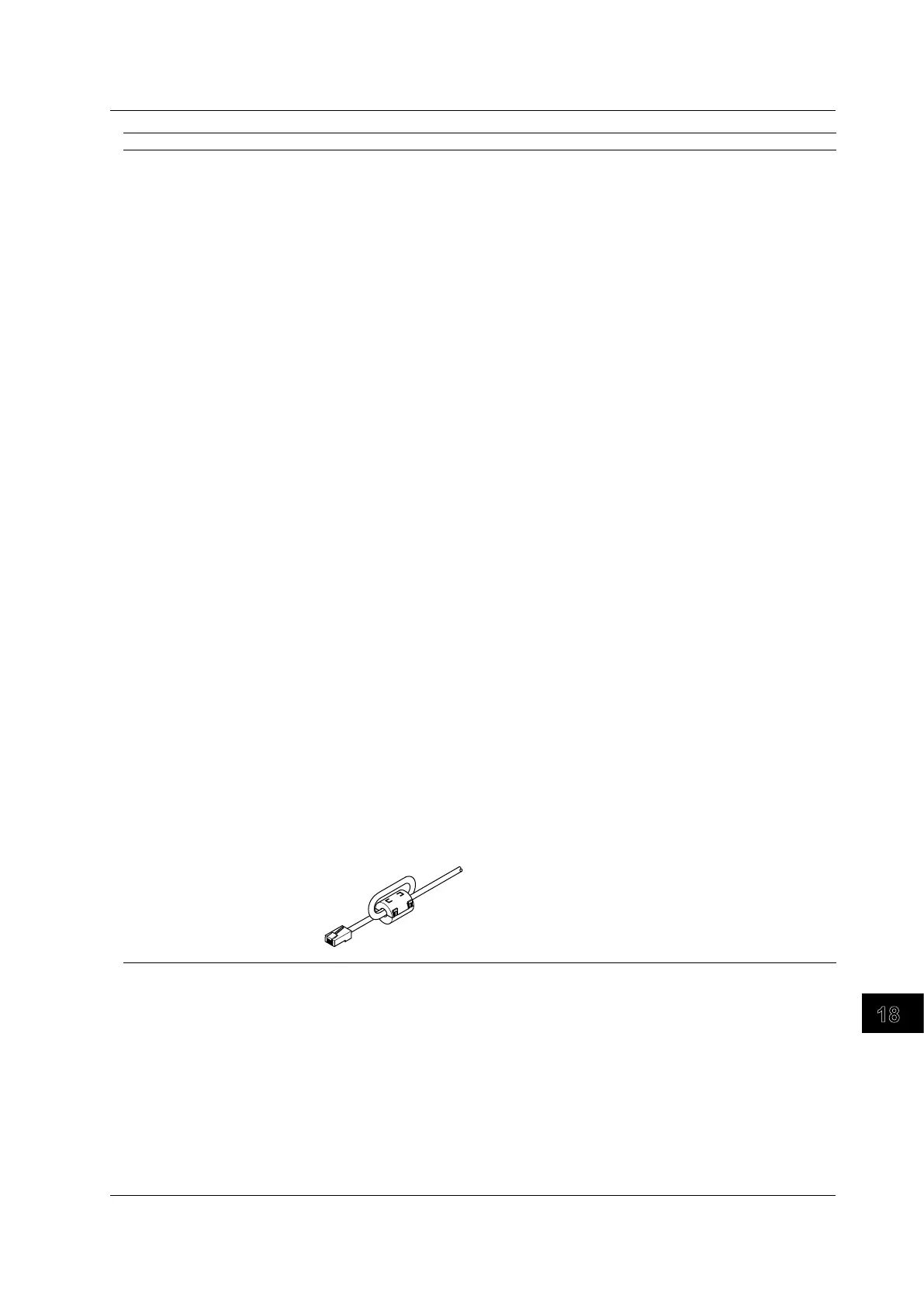
GO/NO-GO output terminal
Use a GO/NO-GO cable (YOKOGAWA model 366973, sold separately) and wind the cable
twice around the ferrite core (TDK: ZCAT2035-0930A, YOKOGAWA: A1190MN) on one end
(DL6000/DLM6000 end). See the figure below.
Ethernet interface connector
Use a Ethernet interface cable4 and wind the cable twice around the ferrite core (TDK:
ZCAT2035-0930A, YOKOGAWA: A1190MN) on one end (DL6000/DLM6000 end). See the
figure below.
1 The overvoltage category(installation category) is a value used to define the transient overvoltage condition and includes the
rated impulse withstand voltage. The overvoltage category II applies to electrical equipment that is powered through a fixed
installation, such as a switchboard.
2 Measurement category (CAT I) applies to measurement of circuits that are not directly connected to a main power source.
For example, this category applies to measurement of secondary electric circuits in equipment across a transformer. The
estimated transient overvoltage for the DLM2000 is 1500 V.
3 The pollution degree refers to the degree of adhesion of a solid, liquid, or gas which deteriorates withstand voltage or
surface resistivity. Pollution degree 2 applies to normal indoor atmospheres (with only non-conductive pollution).
4 Logic only available on the DLM6000.
5 The 701935 is YOKOGAWA’s Deskew Correction Signal Source.
6 Use cables of length 3 m or less.
7 Only connect to evaluate the DLM6000. Do not use with the DL6000.
18.11 General Specifications
 Loading...


