6-4 IM 701450-01E
Explanation
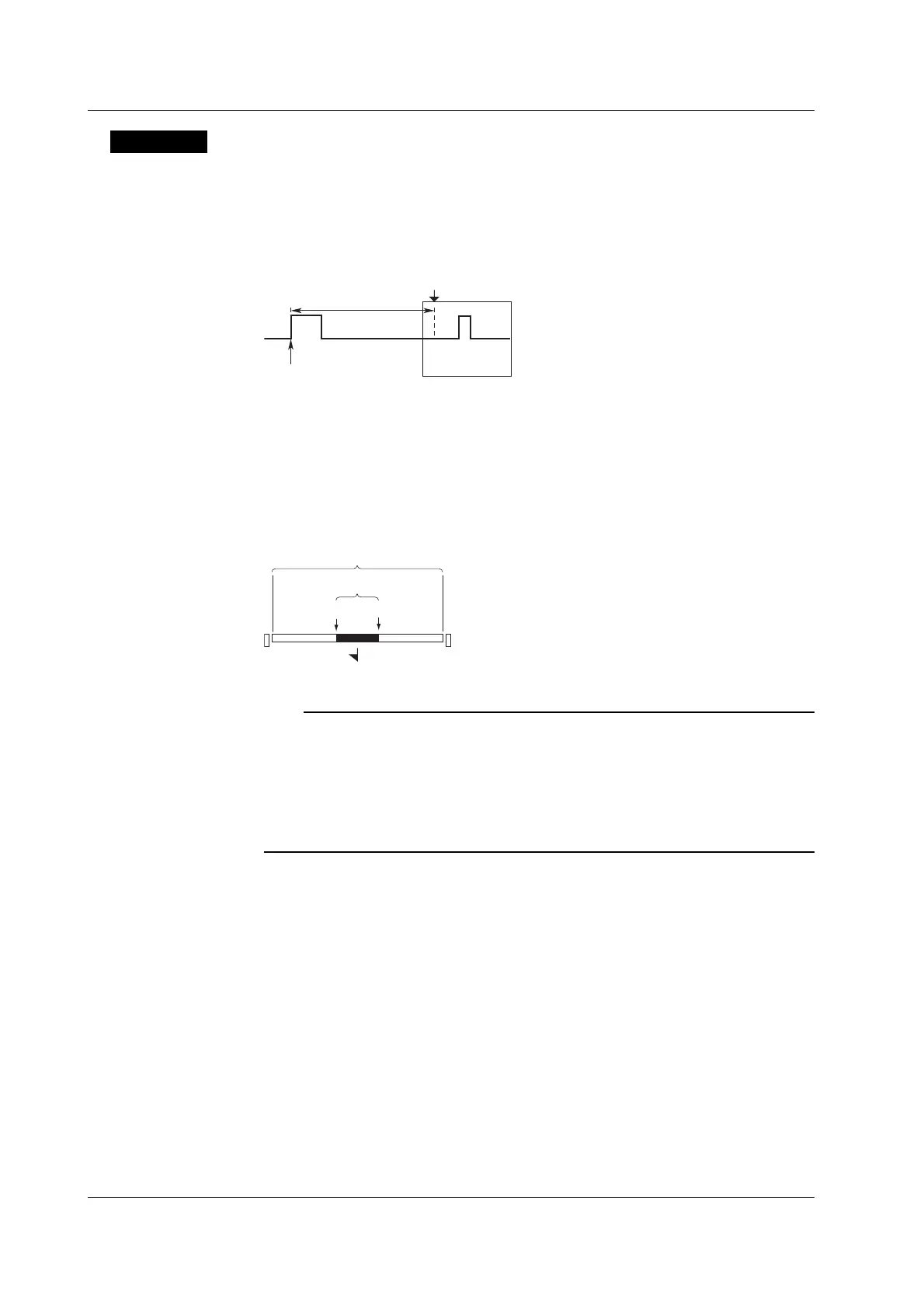
Trigger Position
Trigger position = Trigger point + trigger delay
You can select the location of the trigger position on the screen. If the trigger delay is 0
s, the trigger position and the trigger point match. For the operating procedure of the
trigger delay, see section 6.3.
Delay
Trigger point
T (Trigger position)
Selectable Range of Trigger Position
The trigger position can be set in the range of 0 to 100% (resolution is 0.1%) taking the
display record length (see appendix 1) to be 100%.
Display the Trigger Position
A mark that appears at the top of the screen indicates the trigger position with respect to
the display record length.
Trigger position
0% 100%
T
Specified record length
Display record length
Note
• If you change the trigger position while waveform acquisition is stopped, the new setting will
not become effective until acquisition is started and the waveform is updated.
• Note that cursor time measurements are with respect to the trigger position. Changing the
trigger position therefore changes the measurement values (except when in roll mode
display).
• If you change the T/div setting, the time axis setting is rescaled with respect to the trigger
position.
6.2 Setting the Trigger Position

 Loading...


