3-11
IM 701450-01E
Making Preparations for Measurements
3
3.6 Connecting Logic Probes (Optional)
CAUTION
• The maximum input voltage of the logic probe input is ±40 V (DC + ACpeak) or
28 Vrms when the frequency is 1 kHz or less. Applying a voltage exceeding this
value may damage the logic probe or the DL7400. If the frequency is above 1
kHz, damage may occur even when the voltage is below this value.
• The 8 input lines on each POD have a common ground. In addition, the ground
for the instrument and the ground for each POD are also common. Do not
connect inputs which have different common voltages, as doing so may cause
damage to the DL7400, logic probe, or other connected instruments.
• Make sure to turn OFF the power to the DL7400 before connecting or
disconnecting the 26-pin connector from the DL7400.
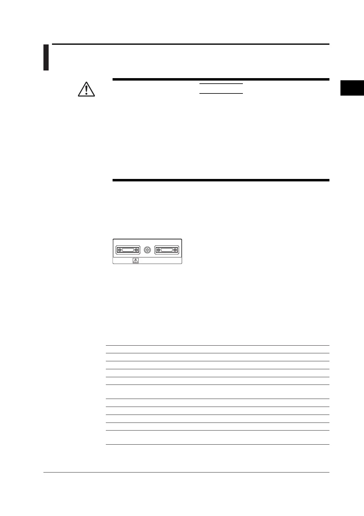
Logic Probe Input Connector
Connect the logic probe (701981) to either of the logic probe input connectors (marked A
and B) on the rear panel.
* When interleave mode is turned ON, the logic signal of connector B can be used as a trigger
source (see section 2.3), but the signal cannot be acquired. For the setup procedure for
interleave mode, see section 7.3.
LOGIC PROBE
A B
About the Logic Probe
The logic probe (701980/701981) connects to the logic probe input connector of the
DL7440/DL7480. When connecting to the measurement point, use the connecting lead
(B9852EJ+A1470JZ, A1471JZ) that comes with the probe. Do not alter the connecting
leads. Doing so may cause the leads from satisfying the specification.
Each pod (A or B) consists of 8 logic input terminals. You can select the threshold level
on the DL7440/DL7480 menu from CMOS (5 V), CMOS (3.3 V), ECL, and user-defined
(see section 5.10).
Logic Input Specifications When Used on the DL7400
Item When using the 701981 When using the 701980
1
Maximum toggle frequency
2
250 MHz 100 MHz
Number of inputs 16 (when two logic probes are used) Same as the 701981
Maximum input voltage
3
±40 V (DC+ACpeak) or 28 Vrms Same as the 701981
Input range ±10 V ±40 V
Maximum sampling rate 1 GS/s (interleave mode OFF) Same as the 701981
2 GS/s (interleave mode ON) Same as the 701981
Threshold level ±10 V (resolution: 0.1 V) ±40 V (resolution: 0.1 V)
Threshold accuracy
2
±(0.1 V + 3% of the setting) Same as the 701981
Minimum input voltage
2
500 mVp-p Same as the 701981
Input impedance Approx. 10 kΩ and 9 pF Approx. 1 MΩ and 10 pF
Preset threshold levels CMOS (5 V) = 2.5 V, CMOS (3.3 V) = 1.6 V, Same as the 701981
ECL = –1.3 V
1 The 701980 can be used only when the firmware version of the DL7400 is 1.30 or later.
2 Under standard operating conditions (see section 17.12) after the warm-up
3 At 1 kHz or less

 Loading...


