14-5
IM 701450-01E
14
Rear Panel Auxiliary I/O Section
14.3 Video Signal Output (VIDEO OUT (VGA))
CAUTION
• Connect the cable after turning OFF the DL7400 and the monitor.
• Do not short the VIDEO OUT (VGA) terminal or apply external voltage to it.
Doing so can cause damage to the DL7400.
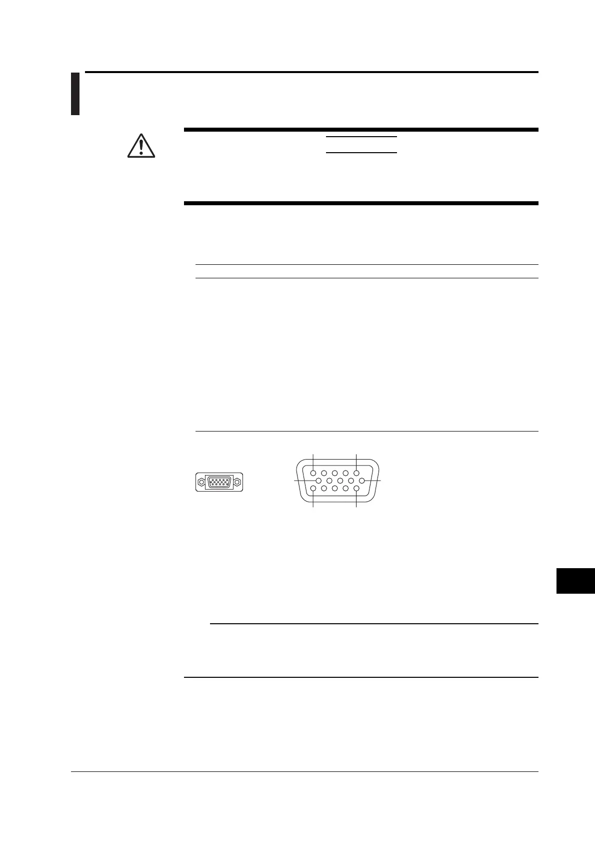
Video Signal Output Connector
The DL7400 display can be output to a monitor through the RGB output. Connectable
monitors are VGA monitors or multi-sync monitors capable of displaying VGA.
Pin No. Signal Name Specifications
1 Red 0.7 Vp-p
2 Green 0.7 Vp-p
3Blue 0.7 Vp-p
4–
5–
6 GND
7 GND
8 GND
9–
10 GND
11 –
12 –
13 Horizontal sync signal Approx. 31.3 kHz, TTL negative logic
14 Vertical sync signal Approx. 60 Hz, TTL negative logic
15 –
VIDEO OUT
(VGA)
6
11
15
15
10
D-Sub 15-pin receptacle
Connecting to the Monitor
1. Turn OFF the DL7400 and the monitor.
2. Connect the DL7400 and the monitor using an analog RGB cable.
3. The screen of the DL7400 appears on the monitor when both the DL7400 and
the monitor are turned ON.
Note
• The RGB video signal is constantly output from the VIDEO OUTPUT terminal.
• The monitor screen may flicker if the DL7400 or another instrument is brought close to the
monitor.
• The edge of the screen may drop out depending on the monitor type.

 Loading...


