1-6 IM 701450-01E
1.3 Display
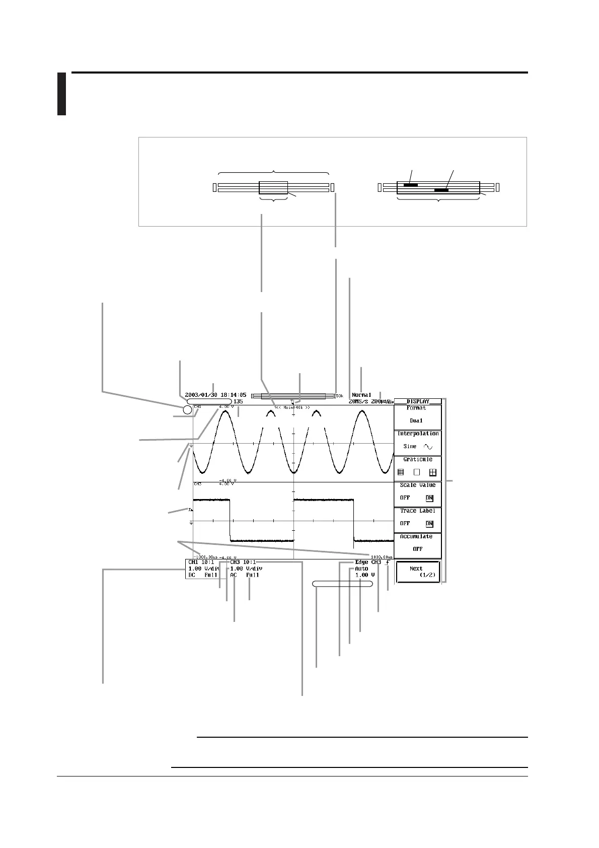
Normal Display Screen
Z1
Z2
50k
50k
Internal processing indication
Indicates the current processing status by the color of
∗
.
Green Computing (power spectrum) or accumulating
history waveforms
Ye llow Automated measurement of parameters in
progress or searching
Blue Sending mail, executing a command of the FTP
server function, or executing an HTTP command
Waveform acquisition count
The length of the
green frame
indicates the ratio of
the display record
length with respect
to the specified
record length.
Record length/display position
Specified record length
<When displaying zoom waveforms>
<When displaying normal waveforms>
Z1 zoom position
Z2 zoom position
Waveform acquisition status
Stopped
Running (acquisition in progress)
Running Pre (acquiring pre data)
Running Post (acquiring post data)
Running Waiting for Trigger
Specified record length. See section 7.2.
Trigger position
mark. See section
6.2.
Display record length
See appendix 1.
Date/time
See section 3.7.
Acquisition mode. See section 7.5.
Normal Normal mode
Env Envelope mode
Avg Averaging mode
BoxAvg Box average mode
If the horizontal axis scale is changed when waveform
acquisition is stopped, the new horizontal axis scale
and sample rate are displayed highlighted at the
position where the acquisition mode is displayed.
Sample rate. See appendix 1.
Horizontal axis scale (time axis T/div)
See section 5.12.
Trigger level mark
See section 2.3.
Ground level mark
See section 2.2.
Vertical position mark
See section 5.3.
Time from the trigger
position to the left and
right ends of the
waveform display frame
Label of the
displayed waveform
See section 8.9.
Scale value
See section 8.8.
Displayed waveform
Vertical axis sensitivity (V/div)
See section 5.2.
Input coupling
See section 5.4.
Bandwidth limit
See section 5.8.
Rectangular frame
Enclosed by a rectangular frame when the channel is
being set by V/div.
If the vertical axis scale is changed when waveform
acquisition is stopped, the new vertical axis sensitivity
is displayed highlighted at the position where the
input coupling and bandwidth limit are displayed.
Comment
Displays the specified comment when printing or
saving the screen image.
Trigger type. See section 2.3 and chapter 6.
Trigger mode. See section 6.1.
Trigger source
See section 2.3 and chapter 6.
Trigger slope
See section 2.3 and chapter 6.
Trigger level. See section 2.3 and chapter 6.
Probe attenuation/current-to-voltage
conversion ratio. See section 5.5.
Setup menu
Display position
Display position of the
normal waveform
Green
frame
Green
frame
Note
In some cases, the LCD on the DL7400 may include a few defective pixels. For details, see
section 17.5.

 Loading...


