3-10 IM 701450-01E
3.5 Compensating the Probe (Phase Correction)
CAUTION
Do not apply external voltage to the probe compensation signal output terminal.
This may cause damage to the internal circuitry.
Procedure
1. Turn ON the power switch.
2. Connect the probe to the input terminal to which the signal is to be applied.
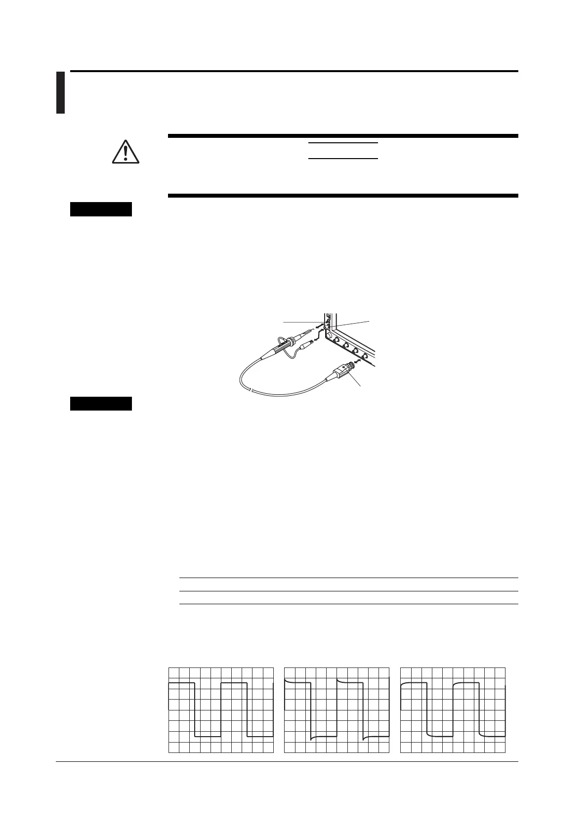
3. Connect the tip of the probe to the probe compensation signal output terminal
and the ground wire to the functional ground terminal.
4. Perform auto setup according to the procedures given in section 4.5.
5. Insert a flat-head screwdriver to the phase correction hole and turn the variable
capacitor to make the displayed waveform a correct rectangular wave.
Phase correction hole
Functional ground terminal
Probe compensation
signal output terminal
Explanation
Necessity of Phase Correction of the Probe
If the input capacity of the probe is not within the adequate range, the gain across
different frequencies will not be uniform. Consequently, waveforms cannot be displayed
correctly. In addition, the input capacitance of each probe is not constant. Thus, a
variable capacitor (trimmer) is provided for making adjustments. Phase correction refers
to the act of adjusting the probe using this capacitor. When using the probe for the first
time, make sure to perform phase correction.
Furthermore, the appropriate input capacitance varies depending on the oscilloscope
channel. Therefore, probe compensation is also required when the probe is switched
from one channel to another.
Probe Compensation Signal
The probe compensation signal output terminal outputs the following rectangular wave signal.
Frequency Approx. 1 kHz
Amplitude Approx. 1 V
Differences in the Waveform due to the Phase Correction of the Probe
Correct waveform Over compensated
(the gain in the high
frequency region is up)
Under compensated
(the gain in the high
frequency region is low)

 Loading...


