2-15
IM 701450-01E
2
Explanation of Functions
2.4 Waveform Acquisition and Display Conditions
Record Length <For the setup procedure, see section 7.2>
The term
record length
refers to the number of data points acquired per channel in the
acquisition memory. The record lengths that can be specified (specified record length) are
1 kW (1000 points), 10 kW, 50 kW, 100 kW, 250 kW, 500 kW, 1 MW, 2 MW, 4 MW, 8 MW,
and 16 MW. The maximum record length that can be specified varies depending on the
model and interleave mode setting.
Displayed record length
refers to the number of these
data points that are actually displayed on the screen. When the time axis setting is
changed, the sample rate and display record length change (see appendix 1).
In most cases, the displayed record length is identical to the (acquisition) record length.
For certain time-axis settings, however, the lengths become different (see appendix 1).
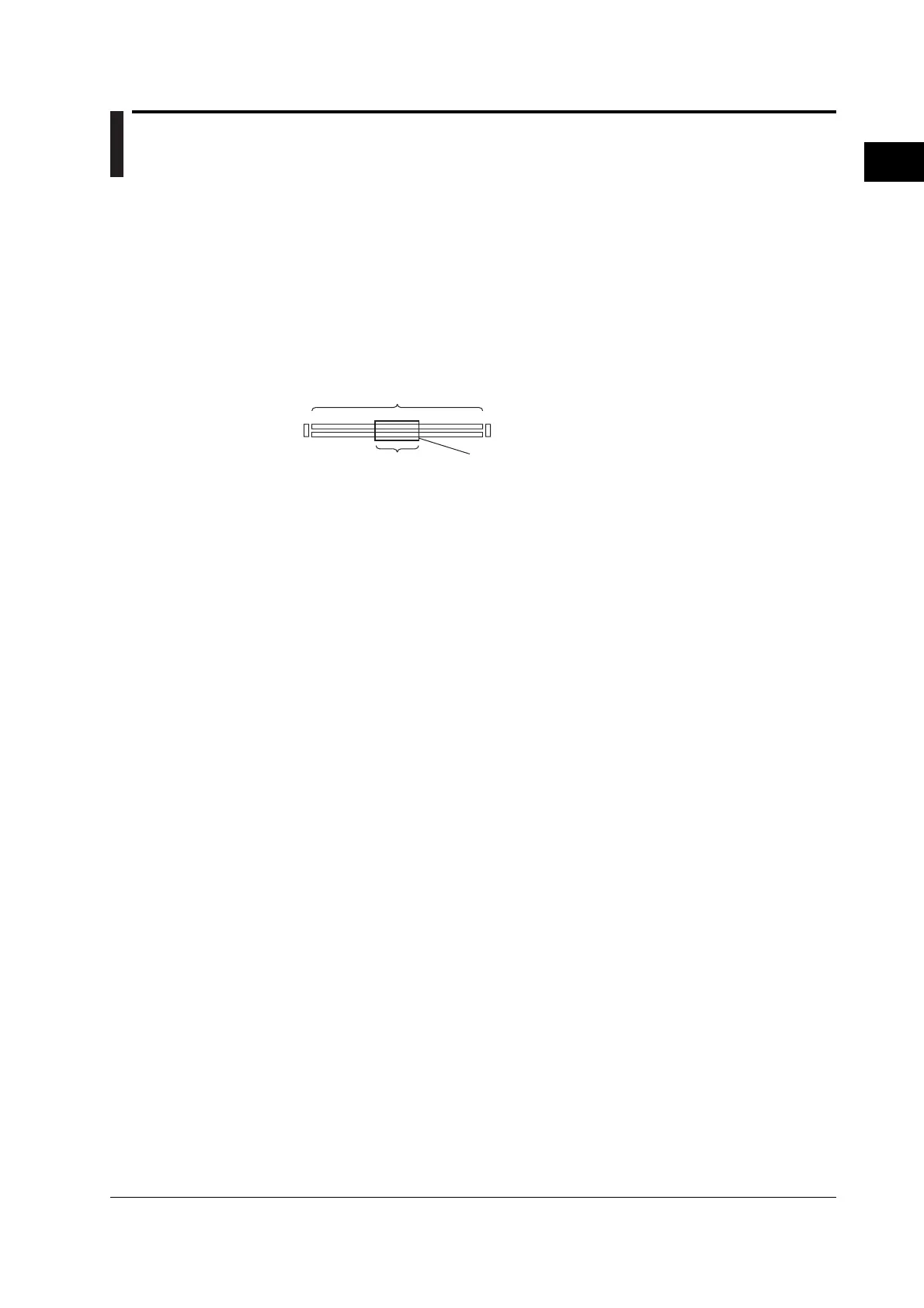
Specified record length
Display position
Green frame
50k
The length of the green frame indicates the
ratio of the display record length with
respect to the specified record length.
Interleave Mode <For the setup procedure, see section 7.3>
This mode allocates the memory of even channels to the odd channels to enable the use
of twice the normal memory. When interleave mode is turned ON, even channels can no
longer be used, but parameters such as the history memory, acquisition count of
sequential store, and record length can be set twice their normal values. In addition,
since two A/D converters can be used to sample a single input signal and raise the
maximum sample rate, a sample rate of 2 GS/s can be achieved in realtime sampling
mode. For the relationship between interleave mode, time axis, record length, and
sample rate, see appendix 1.
Sampling Mode <For the setup procedure, see section 7.4>
As explained in “Relationship between the Time Axis Setting and Sampling Mode” in
section 2.2, the sampling mode can be switched between realtime sampling mode and
repetitive sampling mode depending on the time axis and record length settings. The
time axis range that allows repetitive sampling mode varies depending on the acquisition
setting. For details, see appendix 1.
Acquisition Mode <For the setup procedure, see section 7.5>
When storing sampled data in the acquisition memory (see “Signal Flow” in section 2.1),
it is possible to perform processing on data and display waveforms based on the
processed data. The following four types of data processing are available.
Normal Mode
In this mode, sampled data is stored in the acquisition memory without processing.

 Loading...


