13-31
IM 701450-01E
13
Ethernet Communications (Optional)
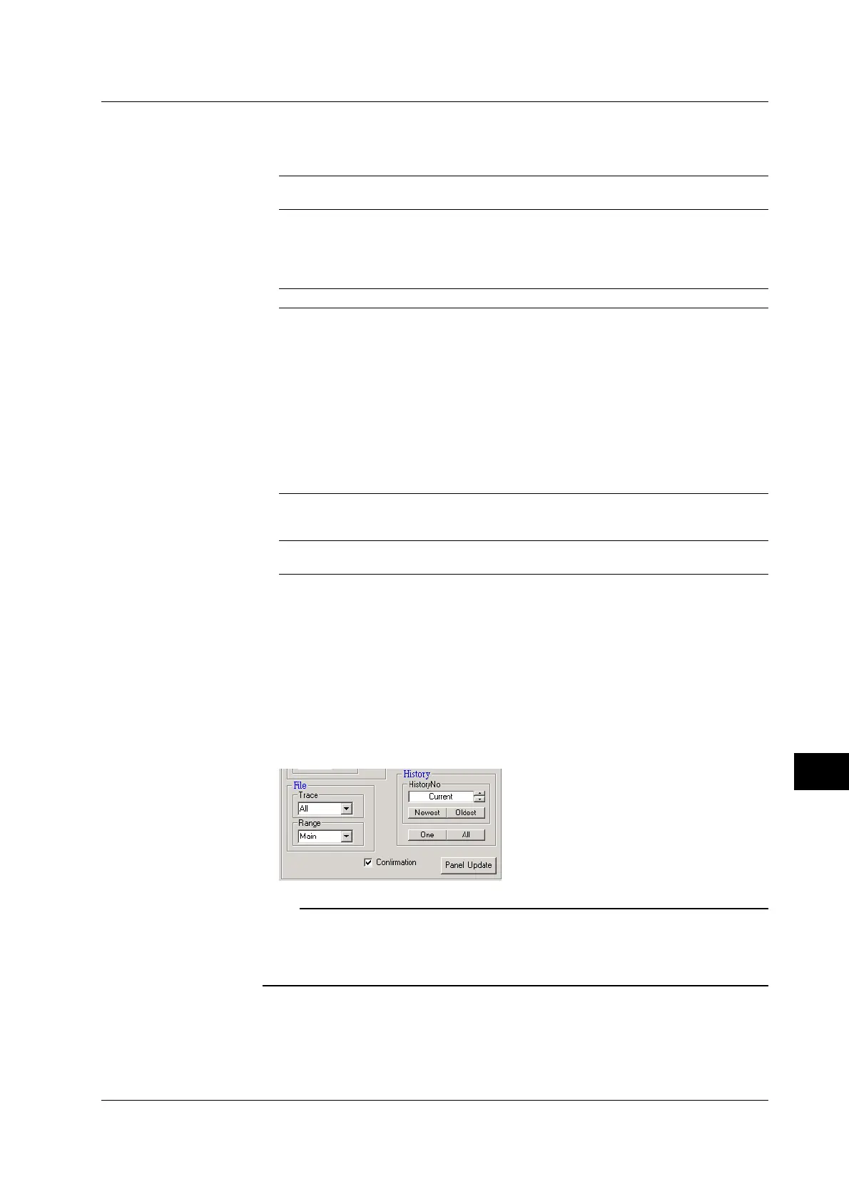
• Selecting the Waveforms to Be Saved (File)
Selecting the Target Waveform (Trace)
You can select the waveforms to be saved using the trace box.
All (all waveforms), 1 to 8 (channels 1 to 8)
1
, Math1, Math2 (computed waveforms), Pod A
2
, and
Pod B
2
1 All, 1 to 4 (channels 1 to 4) on the DL7440.
2 Pod A and Pod B apply if the logic input option is installed.
Selecting the Save Area (Range)
Select the area in which the target waveform to be saved is displayed.
Main, Z1, Z2, or Z1_Z2 (displayed as Z1&Z2 on the DL7400 menu)
* For the meanings of the selections, see the explanation in section 12.8.
• Setting the History Waveform Display
Selecting by History Waveform Number (History No.)
Specify the number of the history waveform to be displayed.
Selecting the Newest or Oldest Data
You can specify the newest or the oldest waveform among the history waveforms to
be displayed.
Selecting One or All
One
Click One. A single history waveform that is selected by the history waveform number or
selected by newest or oldest is displayed.
All
Click All. All the history waveforms are displayed.
• Updating the Setup Condition (Panel Update)
Click Panel Update. The control panel settings on the Data Capture window (PC) are
updated to match the newest setup condition on the DL7400.
• Automatically Updating the Screen Image (Confirmation)
Select the Confirmation check box. The screen image is automatically updated
using the same conditions as Color-OFF when you change the settings of the above
items that would cause the screen image to change. Clear the check box to not
update automatically.
Note
• You cannot set the history waveform display when the DL7400 is making measurements.
• Setting the history waveform display when there are no history waveforms results in error.
• The timeout time on the PC when controlling the DL7400 is 30 s. Depending on the DL7400
condition, a timeout may occur preventing you from controlling the DL7400.
13.7 Using the Web Server Function

 Loading...


