2-29
IM 701450-01E
2
Explanation of Functions
Cursor Measurements <For the setup procedure, see section 10.5>
Cursors can be placed on the displayed waveform (within the display record length. See
appendix 1) and various types of measured values at the cross point of the cursor and
waveform can be displayed. Four types of cursors are available.
Horizontal Cursors
Two broken lines (horizontal cursors) are displayed on the horizontal axis (X-axis). The
Y-axis values at the cursor positions can be measured. The level difference between
cursors can also be measured.
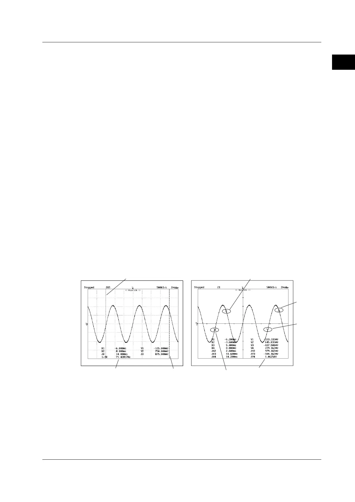
Vertical Cursors
Two broken lines (vertical cursors) are displayed on the vertical axis (Y-axis). The time
(X-axis values) from the trigger point to each vertical cursor and the time difference
between the vertical cursors can be measured. In addition, the signal level (Y-axis
value) at each cursor position and the level difference between the cursors can be
measured.
Marker Cursors
Four markers are displayed on the selected waveform. The level (Y-axis value) at each
marker, the time (X-axis value) from the trigger position, and the level difference and
time difference between markers can be measured.
Angle Cursors
Measurements can be made by converting the time axis values into angles. The zero
point (position of reference cursor Ref1) and the end point (position of the reference
cursor Ref2) are set on the X-axis and an angle (reference angle) is assigned to the
width of Ref1 and Ref2. The positions of the two angle cursors (Cursor1 and Cursor2)
can be converted into angles from the specified reference angle and measured.
Cursor measurement values
Marker 1
Marker 3
Marker cursor
Vertical cursor
Cursor 2
Cursor 1
Cursor measurement values
Marker 2
Marker 4
2.6 Analyzing and Searching Waveforms

 Loading...


