3-8 IM 701450-01E
Miniature Passive Probe (701941) Specifications after Probe Phase Correction
(On models with the /EX4 option, 701941 passive probes are provided in place of
700988 passive probes.)
Item Specifications Conditions
Input resistance/capacity 10 MΩ ± 2% / approx. 10 pF When used on the DL7400
Attenuation 10:1 ±3% When used on the DL7400
Frequency range DC to 500 MHz When used on the DL7400
Rise time Within 700 ps When used on the DL7400
Maximum input voltage 400 Vrms* 500 kHz or less
For the maximum input voltage
when 500 kHz is exceeded, see the
manual that comes with the probe.
Connector type BNC –
Cable length 1.2 m –
* This probe complies with the following measurement categories of IEC 61010-031.
Measurement category I 400 Vrms (transient overvoltage: 1250 V)
Measurement category II 300 Vrms
Precautions to Be Taken When Using Probes Other Than Those Provided with the
Instrument
• When measuring a signal containing frequency components near 500 MHz, use a
probe with a frequency range of 500 MHz or higher.
• Correct measured values cannot be displayed when using a probe with an attenuation
other than 1:1, 10:1, 100:1, and 1000:1.
• For current probes, use 700937, 701930, 701931, 701932, or 701933 by YOKOGAWA.
Setting the Probe Attenuation/Current-to-Voltage Conversion Ratio
Follow the procedures given in section 5.5 and set the attenuation/current-to-voltage
conversion ratio of the DL7400 according to the probe attenuation/current-to-voltage
conversion ratio. Correct measured values can be displayed only if the setting is correct.
When Using the FET Probe, Current Probe, or Differential Probe
When using FET probes (700939), current probes (700937, 701930, 701931,701932, or
701933), or differential probes (701920 or 701922) made by YOKOGAWA, use the
probe power supply on the rear panel of the DL7400.
CAUTION
Do not use the probe power supply terminals on the rear panel of the DL7400
for purposes other than supplying power to the probes (700939, 700937,
701930, 701931, 701932, 701933, 701920, or 701922). Doing so may damage
the DL7400 or the device connected to them.
Precautions to Be Taken When Using the FET Probe, Current Probe, or Differential
Probe
When connecting FET probes (700939), current probes (700937, 701930, 701931,
701932, or 701933), or differential probes (701920 or 701922) to the probe power supply
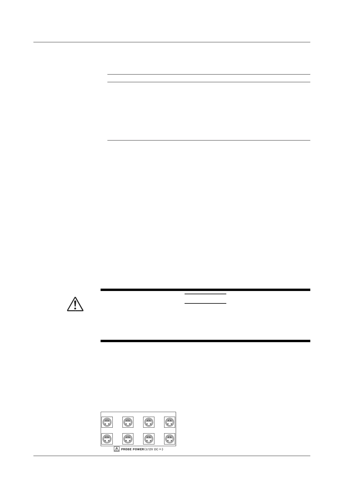
terminal on the rear panel, make sure that the current does not exceed the range shown
below. Otherwise, the DL7400 operation may become unstable due to the activation of
the excessive current protection circuit of the power supply.
ABCD
EFG
H
The following current values must be less than
or equal to ±500 mA.
• Total current consumption of A and E
• Total current consumption of B and F
• Total current consumption of C and G
• Total current consumption of D and H
(E, F, G, and H correspond to the DL7480 with
the /P4 option installed.)
3.4 Connecting the Probe

 Loading...


