1-8
IM DLM4038-02EN
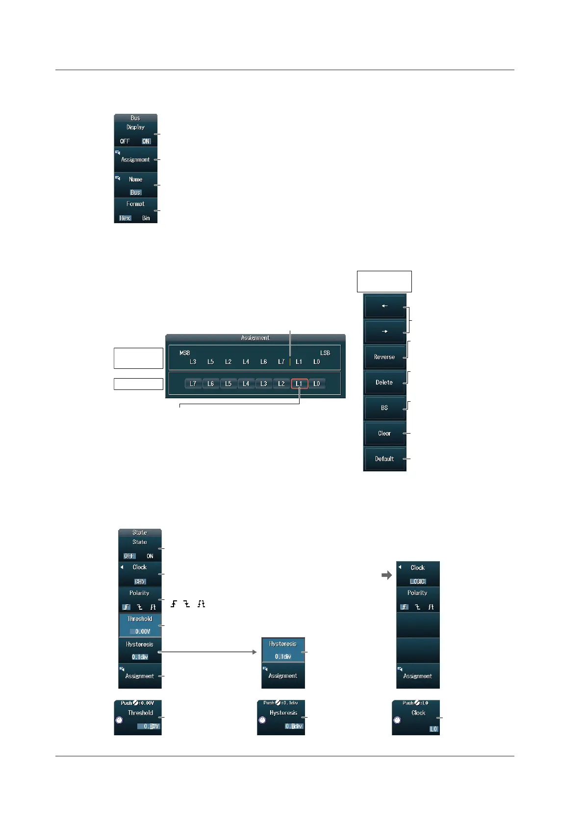
Bus Settings (Bus)
Press the Bus soft key to display the following menu.
Set the format (Hex, Bin).
Set the label.
Set bus bit assignments.
Turns the bus display on and off
Bus Bit Assignments
Press the Assignment soft key to display the following screen.
Assignment
location
Bits
Assignment
edit menu
Move the cursor.
Delete
Deletes the bit to the right of
the cursor
Restores the default
settings
Clears everything
Order reversal
Reverses the MSB to LSB
order of the bits
Backspace
Deletes the bit to the left of
the cursor
Cursor
Assigned bit
Use the jog shuttle to select the bit to assign
to the right of the assignment location cursor.
1.
Press SET to assign the bit.
2.
State Settings (State)
Press the State soft key to display the following menu.
Turns the state display on and off
Set the state assignment.
When the clock source
is LOGIC
Set the clock source during state
display (CH5 to CH7, LOGIC).
Set the clock
source bit.
Set the clock source polarity
( , , ).
Clock source
detection level
Clock source
hysteresis
Set the clock
source hysteresis.
Set the clock source
detection level.
1.2 Setting the Vertical Axis for 8-bit LOGIC(L)
 Loading...


