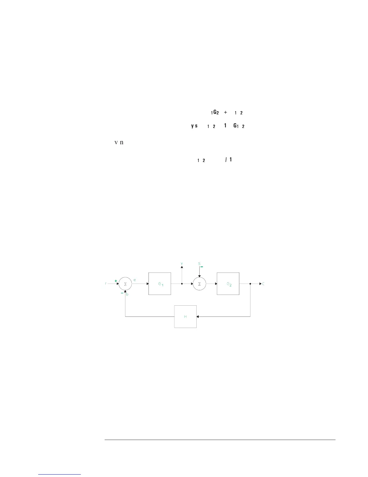
Another method is to measure the closed loop frequency response function. A
summing junction is used to add a stimulus signal (s) to the loop and the
measurement is made at points y and s. See figure 5-5. You then can calculate
the open loop frequency response function.
Usingtheblockdiagramshowninfigure5-5,wecansolvefory/s.
y = -yG
1
G
2
H+sG
1
G
2
H
y/s = G
1
G
2
H/(1+G
1
G
2
H)
Solving for the open loop response
G
1
G
2
H = (y/s) / (1 - (y/s))
To display the open loop transfer function, use the frequency response
measurement data to get y/s and then use a math function to calculate the open
loop response. It is important to check the measurement results before math
operations are performed. The math functions can also be used to “correct” a
measurement which contains phase and gain offsets. To check for these gain
and phase offset, you need to look at the measured value of y/s. Since
y/s = G
1
G
2
H/1 + G
1
G
2
H, we expect to see a gain of 0 dB for lower
frequencies, where G
1
G
2
H is large and the phase should be approaching 0
degrees.
Figure 5-5.
Block Diagram for Closed Loop Frequency
Agilent 35670A
Operator's Guide Measuring Control Systems
5-13