To measure gain and phase margin
1 Measure the open loop response.
2 Press [
Marker Fctn
][
GAIN/PHAS MARGINS
].
3 Press [
START FREQUENCY
] <number> <unit>.
or
Move the marker to the desired start frequency.
4 Press [
STOP FREQUENCY
] <number> <unit>.
or
Move the marker to the desired stop frequency.
5 Press [
COMPUTE MARGINS
].
Gain margin is the magnitude below 0 dB (gain =1) at the frequency at which phase
equals -180 °. Phase margin is the phase above -180° at which gain equals 1. Gain
crossover is the frequency at which gain equals 1.
The compensator gain will be determined by the gain required to achieve gain
crossover at a desired frequency. Gain and Phase values at that frequency will indicate
the amount of gain and phase for the compensator design. For example, if the
specification is to have a gain-crossover frequency of 265 Hz and a phase margin of
40 °± 5°, and the marker measurements show a gain of -9.15 dB and phase of -178° at
265 Hz, the compensator will need 9.15 dB of gain and 38 ° of phase shift
(180 − 178 =2; 40 −2 = 38).
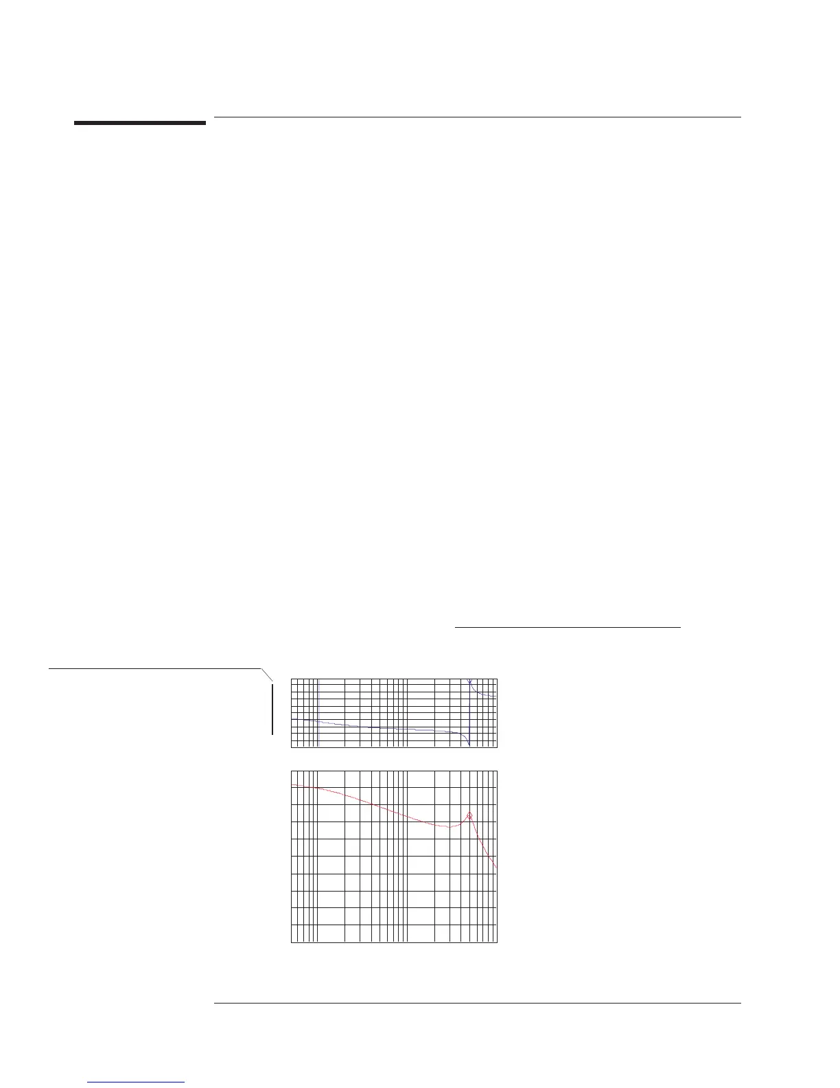
Gain:15.8522dB Phase:133.3102Deg
51.2Hz 10kHz
A: FreqResp2/1 X:5.0374 kHz Y:178.62 deg
180
deg
-180
Phase
36
deg
/div
X:5.0374 kHz Y:-15.871dB
B: Freq Resp2/1
10
dB
-90
dB
dBMag
10
dB
/div
MarkerFcn
[Gain/Phs]
Trace: A GnXovr: 104.36Hz
Ps Xovr: 5.0374kHz
Crossover frequency value
appears in mini state.
Crossover frequency
indicated by solid band
markers.
Agilent 35670A
Measuring Control Systems Operator's Guide
5-16

 Loading...


