6 Specify the tachometer parameters.
Press [
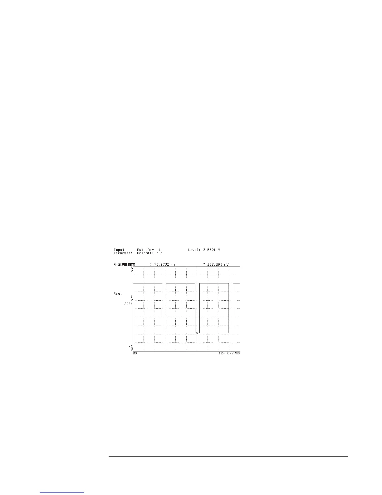
Input
][
TACHOMETR SETUP
].
If the waveform’s high or low points fall outside a +/- 4 V range, press
[
TRG RANGE +/- 20 4
] to highlight 20.
Press [
LEVEL
] <number> <unit> to specify the level at which you want the analyzer to
detect the tachometer signal.
If you want the analyzer to detect the falling (negative) edge of the waveform, press
[
SLOPE POS NEG
] to highlight NEG.
Press [
TACH PULS PER REV
] <number> [
ENTER
] to specify the number of tachometer
pulses produced for each revolution of the device-under-test (DUT).
7 Verify the tachometer setup.
Press [
TACHDATAONOFF
] to highlight ON.
Check to be sure that the tachometer readout—located at the top of the display— is
stable.
You should specify a level and slope at which the tachometer signal is fairly
“clean”—that is, a given pulse of the signal should pass through the specified level in
the specified direction only once. If this is not possible, you can use [
HOLDOFF TIME
]
to force the analyzer to ignore multiple passes through the same level. Enter a value
that is just long enough to ensure that the analyzer ignores multiple passes through the
same trigger level on a given pulse of the tachometer signal.
Agilent 35670A
Operator's Guide Measuring Rotating Machinery
1-9