4 Specify the triggering and averaging parameters.
Press [
Trigger
][
CHANNEL 1 2 3 4
] to highlight 1.
Press [
TRIGGER SETUP
][
CHANNEL LEVEL
]<number>[
PERCENT %
]
or
Press <number> <unit>.
Press [
CHANNEL 1 DELAY
][
+/-
] <number> <unit>.
Press [
CHANNEL 1 2 3 4
] to highlight 2.
Press [
CHANNEL 2 DELAY
][
+/-
] <number> <unit>.
Press [
Avg
], then press [
AVERAGE ON OFF
] to highlight ON.
5 Configure the display.
Press [
Trace Coord
][
X-AXIS LIN LOG
] to highlight LIN.
Press [
Active Trace
][
B
].
Press [
Trace Coord
][
PHASE
].
Press [
Active Trace
][
AB
].
Press [
Scale
], then press[
AUTOSCALE ON OFF
] to highlight ON.
6 Measure the DUT.
Press [
Start
].
Slowly tap the device 10 times with the impact hammer at or near the accelerometer.
If your hammer taps consistently result in overloads, increase the input ranges in step 3
until overloads no longer occur.
Specifying a trigger delay in step 4 allows you to see the leading edge of the
hammer tap.
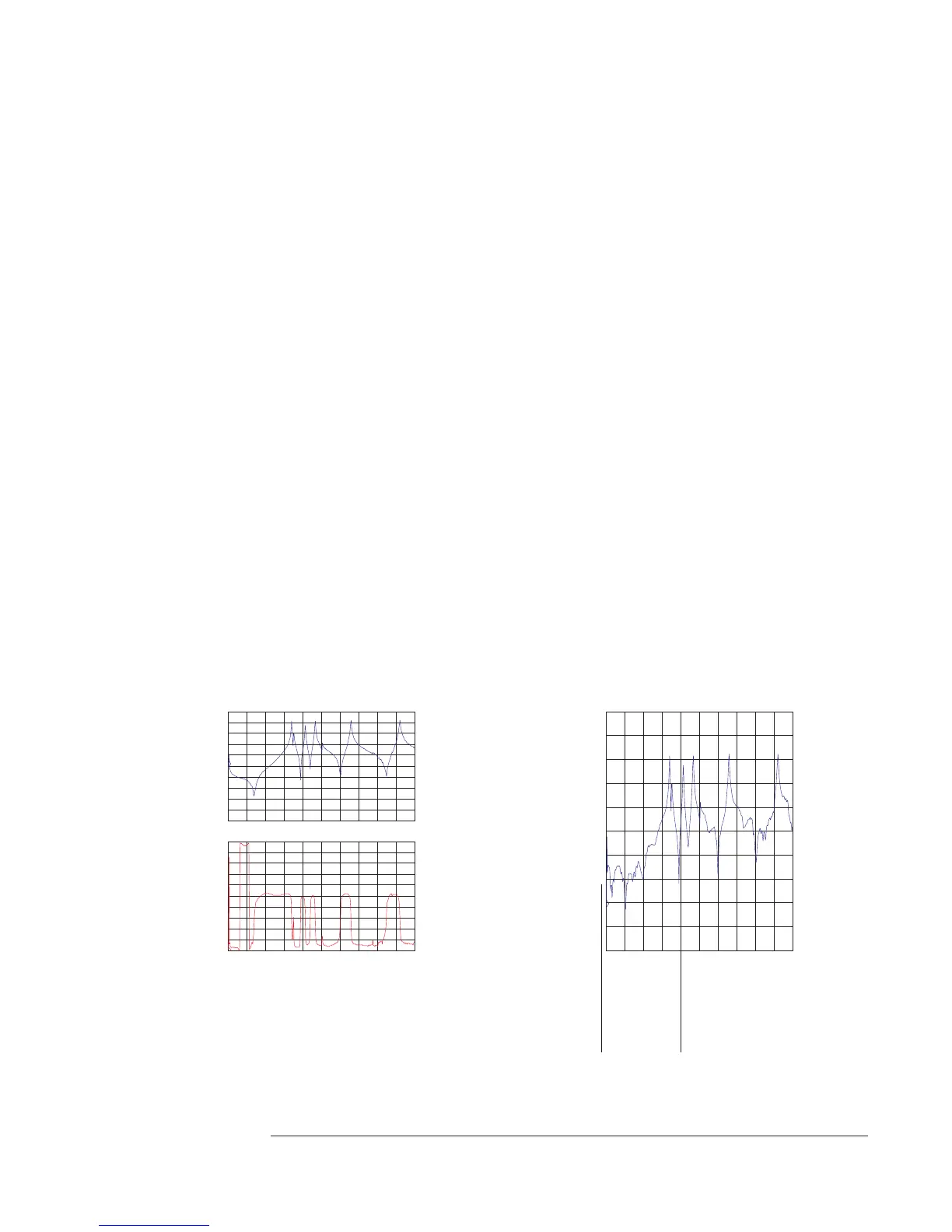
0Hz 3.2kHzAVG: 10
A: FreqResp2/1 X:0 Hz Y:2.58684dB
50
dB
-50
dB
dBMag
10
dB
/div
X:0 Hz Y:-180 deg
B: Freq Resp2/1
180
deg
-180
deg
Phase
36
deg
/div
0Hz 3.2kHzAVG: 10
Trac Coord
[FFT]
A: dBMag B: Phase
C: Real D: Real
A: FreqResp2/1 X:0 Hz Y:-20.464dB
0Hz 3.2kHzAVG: 10OVLD
60
dB
-40
dB
dBMag
10
dB
/div
Avg
[FFT]
Type: RMS Number:10
UpdateRt: 5 Overlap:0 %
Indicates an overload is
included in the average
measurement.
Overload causes distortion
in the frequency response.
Agilent 35670A
Operator's Guide Measuring Structures
2-11