82
S:\Hp8960\E1962B CDMA 2000\Pi Release\Reference Guide\Chapters\cdma2000_conf_meas.fm
Measurement Related Configuration
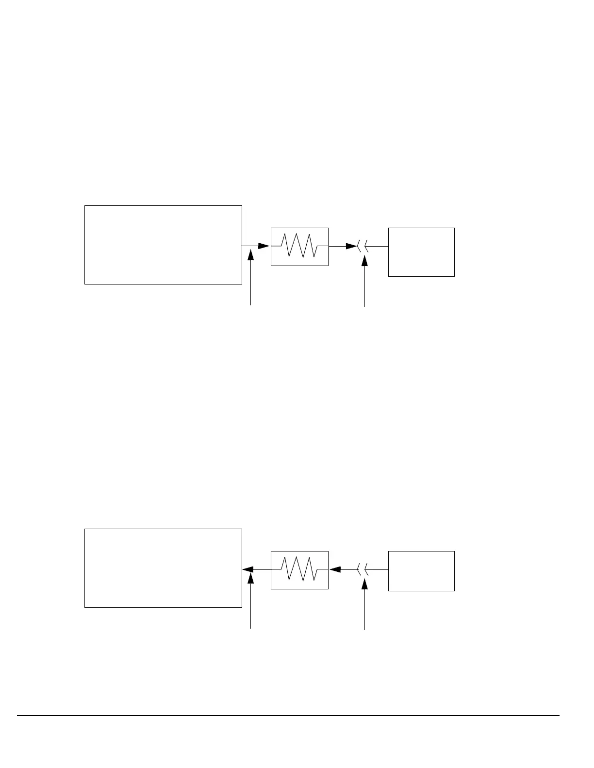
Mobile Station Receiver Example
When you set a transmit power level, the test set uses the amplitude offset value to adjust the power so that
the test set’s transmit power level refers to the power level received at the mobile station.
For example, with the test set’s transmit power set to
−85 dBm and a −3 dB amplitude offset the actual power
level transmitted from the test set will be automatically offset to
−82 dBm. With a 3 dB loss in the signal path
the mobile station will receive
−85 dBm, the actual setting.
Figure 10. Amplitude Offset Mobile Station Receiver Example
Mobile Station Transmitter Example
When you measure power from the mobile station, the displayed and queried values are offset to show the
level at the mobile station.
For example, with the mobile station transmitting 12 dBm and a
−3 dB amplitude offset is entered, the
measured power at the test set would be 9 dBm. The displayed power level is automatically adjusted to 12
dBm to show the level at the mobile station.
If the expected power, which can be set manually or automatically (see “Manual vs. Automatic Receiver
Control” ) is 12 dBm, the test set’s internal hardware adjusts itself to receive 9 dBm which is the actual power
from the mobile station after 3 dB loss in the network.
Figure 11. Amplitude Offset Mobile Station Transmitter Example
Agilent 8960
Transmit Power setting = –85 dBm
Amplitude offset = –3 dB
–3 dB network
(bidirectional)
Mobile
Power = –82 dBm Power = –85 dBm
Station
Agilent 8960
Expected Power setting = 12 dBm
Amplitude offset = –3 dB
–3 dB network
(bidirectional)
Mobile
Power = 9 dBm Power = 12 dBm
Signal Flow
Station

 Loading...


