83
S:\Hp8960\E1962B CDMA 2000\Pi Release\Reference Guide\Chapters\cdma2000_conf_meas.fm
Measurement Related Configuration
Amplitude Offsets Between Frequency Settings
If mobile station testing is performed at frequencies that do not have amplitude offsets assigned to them, the
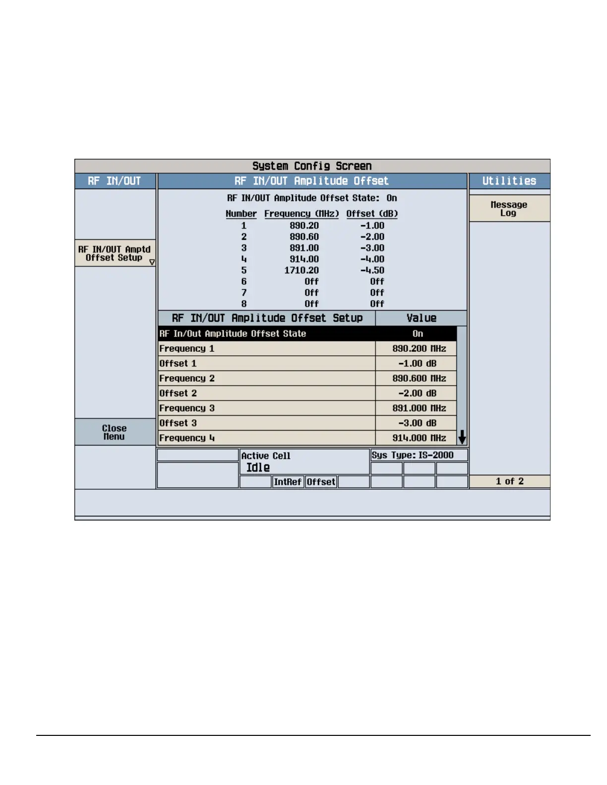
test set will estimate an amplitude offset based on the nearest settings. For example, the following screen
shows five amplitude offsets for frequencies ranging from 890.2 MHz to 1710.2 MHz.
Figure 12. RF IN/OUT Amplitude Offset Setup
For test frequencies between the lowest (890.2 MHz) and highest (1710.2 MHz) frequency points that are not
entered in the table, the test set will calculate offsets using piece-wise linear interpolation.
The graph shown in Figure 13. is a conceptual representation of the test set’s amplitude offset configuration
using the settings from the RF IN/OUT Amplitude Offset table in Figure 12. “RF IN/OUT Amplitude Offset
Setup”. Each of the five points are shown on a non-scaled frequency versus amplitude offset graph. At a test
frequency of 890.4 MHz, which is midway between point number one (-1 dB) and point number two (-2 dB) the
test set applies an offset of -1.5 dB. Be aware that since amplitude offsets are in units of dB, this piece-wise
linear interpolation does not produce a linear transition from point to point.

 Loading...


