Chapter 15 509
Measurement Examples
Measuring an Unbalanced and Balanced Bandpass Filter
15. Measurement Examples
Measuring an Unbalanced and Balanced Bandpass Filter
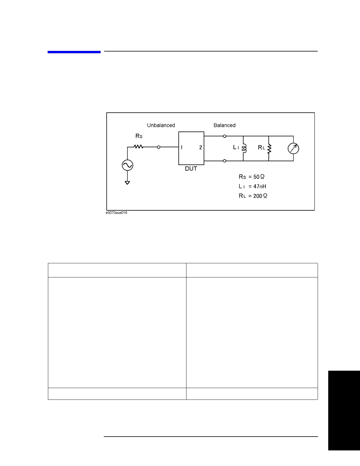
This section introduces an example of actually evaluating the unbalanced and balanced
SAW bandpass filter with a center frequency of 942.5 MHz.
Figure 15-25 shows the
measurement circuit in the condition for evaluating a DUT.
Figure 15-25 Measurement circuit
Evaluation Steps
Here, the DUT is evaluated by following the steps described in Table 15-6.
Table 15-6 Evaluating the Deviation from a Linear Phase
Step Description
“1. Connecting the DUT” on page 510 The DUT is connected.
“2. Setting the Measurement Conditions” on
page 511
The measurement conditions are defined.
“3. Performing Calibration” on page 512 The full 3-port calibration is executed.
“4. Setting a Balance Conversion Topology” on
page 513
The balance conversion topology is specified.
“5. Selecting Measurement Parameters” on page 513 The mixed-mode S-parameters are selected.
“6. Extending the Calibration Plane (removing the
cause of error)” on page 515
The calibration reference plane is extended.
“7. Setting the Port Reference Impedances” on
page 515
The port reference impedances are specified.
“8. Adding a Matching Circuit” on page 517 A matching circuit is added.

 Loading...


