Chapter 7 303
Fixture Simulator
Determining the Characteristics that Result from Adding a Matching Circuit
to a Differential Port
7. Fixture Simulator
Determining the Characteristics that Result from Adding a
Matching Circuit to a Differential Port
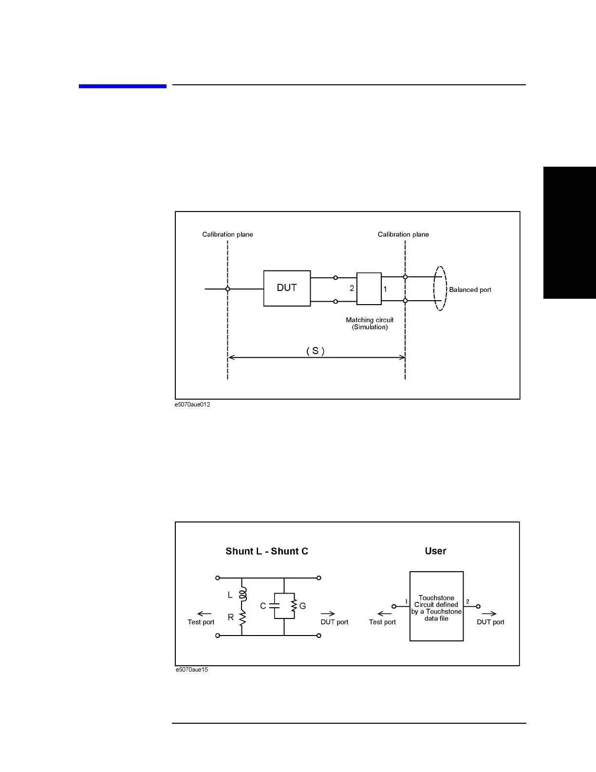
You can obtain the characteristics resulting from the pseudo addition of a balance matching
circuit to a balanced port created by balance-unbalance conversion. By using the matching
circuit function, you can obtain the characteristics resulting from the addition of an
arbitrary matching circuit for each test port (
Figure 7-18).
Figure 7-18 Balance matching circuit function
Define the matching circuit to be added by one of the following methods:
• Use a predetermined circuit model and specify the values for the elements in the circuit
model.
• Use a user file (in two-port Touchstone format) to define the matching circuit to be
added.
Figure 7-19 shows the circuit models used in defining a balance matching circuit.
Figure 7-19 Circuit models used to define balance matching circuit

 Loading...


