522 Chapter 15
Measurement Examples
Evaluating Transmission Characteristics of a Front End Module
1. Determining Measurement Conditions
In this example, perform measurement under the measurement conditions in Table 15-9.
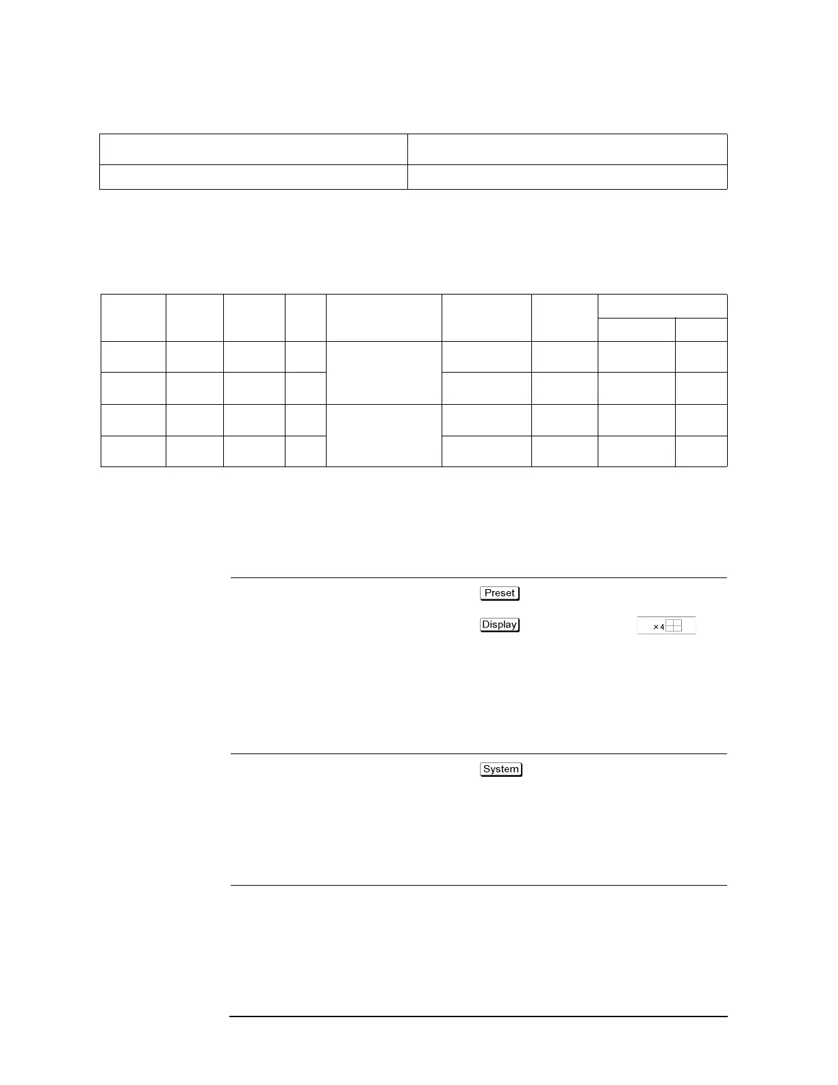
Table 15-10 Sweep conditions
Channel Start
frequency
Stop
frequency
NOP Test port assignment Control line Meas.
parameter
Calibration
Type Port
1 400 MHz 1.4 GHz 201 Port 1 - Port A
Port 2 - Port T1
Port 3 - Port R1+
Port 4 - Port R1-
Line 1: Low
Line 2: High
S12 Full 2-Port 1,2
2 880 MHz 1 GHz 101 Line 1: Low
Line 2: Low
Sds21 Full 3-Port 1,3,4
3 1.34 GHz 2.34 GHz 201 Port 1 - Port A
Port 2 - Port T2
Port 3 - Port R2+
Port 4 - Port R1-
Line 1: High
Line 2: Low
S12 Full 2-Port 1,2
4 1.665 GHz 2.015 GHz 101 Line 1: Low
Line 2: Low
S31 Full 2-Port 1,3
2. Setting Channel Window Allocation
Set the screen to split into 2 rows and 2 columns to assign channel windows after preset.
Setting Description Key Operation
Execute preset
- OK
Allocate channel windows
- Allocate Channels -
3. Setting the Test Ports
Step 1. Display the E5091A setup menu and select the 9-port model for ID1.
Setting Description Key Operation
Display the E5091A setup menu
- Multiport Test Set Setup
Select the 9-port model for ID1 Test Set 1 - Select Test Set - E5091_9
Step 2. Display the E5091A properties.
Setting Description Key Operation
Display the E5091A properties Property
“10. Executing Measurement” on page 527 Execute the measurement and perform auto scale.
Table 15-9 Evaluation Procedure for 6-port Front End Module
Procedure Description

 Loading...


