Chapter 15 513
Measurement Examples
Measuring an Unbalanced and Balanced Bandpass Filter
15. Measurement Examples
4. Setting a Balance Conversion Topology
Follow the procedure below to set the balanced conversion topology.
Table 15-7
Setting Description Key Operation
Set port 1 on the DUT to unbalanced and port 2
on the DUT to balanced.
- Fixture Simulator - Topology -
Device - SE-Bal (check only)
Set the connecting destination of port 1 on the
DUT (unbalanced) to test port 1 of the
analyzer.
Port 1 (se) - 1 (check only)
Set the connecting destination of port 2 on the
DUT (balanced) to test ports 2 and 3 of the
analyzer.
Port 2 (bal) - 2-3 (check only)
5. Selecting Measurement Parameters
Step 1. Display four traces.
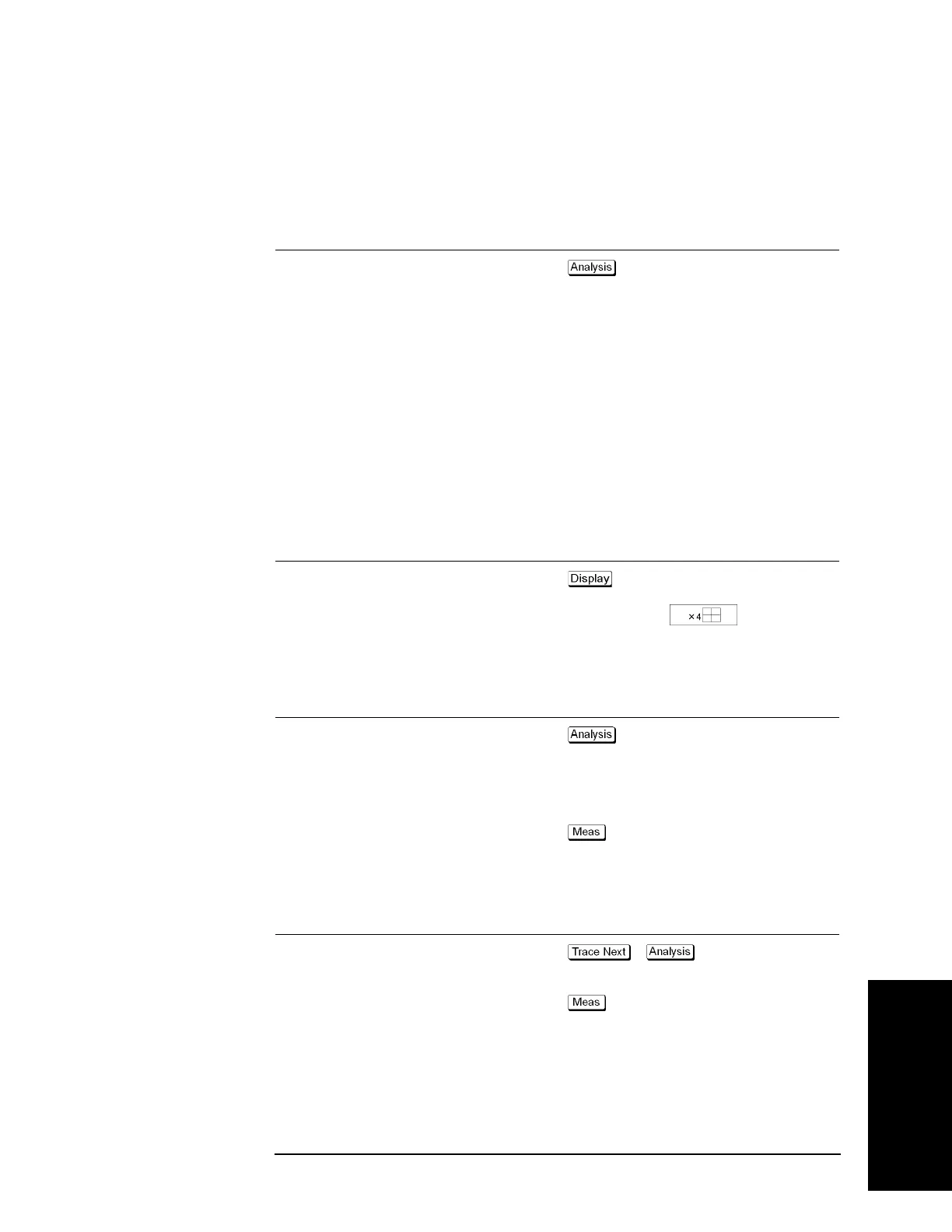
Setting Description Key Operation
Number of traces: 4
- Number of Traces - 4
Trace allocation: 4-part split
Allocate Traces -
Step 2. Set the measurement parameter (mixed mode S-parameter) and data format for trace 1.
Setting Description Key Operation
Fixture simulator: ON
- Fixture Simulator -
Fixture Simulator (turns it ON)
Unbalanced-balanced conversion of trace 1:
ON
BalUn (turns it ON)
Measurement parameter: S
ds21
- Sds21
Step 3. Set the measurement parameter (mixed mode S-parameter) and data format for trace 2.
Setting Description Key Operation
Unbalanced-balanced conversion of trace 2:
ON
- - Fixture Simulator -
BalUn (turns it ON)
Measurement parameter: S
cs21
- Scs21

 Loading...


