Chapter 15 517
Measurement Examples
Measuring an Unbalanced and Balanced Bandpass Filter
15. Measurement Examples
8. Adding a Matching Circuit
Here, add an inductance of 47 nH in parallel to port 2 on the DUT (balanced). It is also
possible to add a matching circuit to the port before unbalanced-balanced conversion. For
more information, see
“Determining the Characteristics that Result from Adding a
Matching Circuit to a Differential Port” on page 303.
Setting Description Key Operation
Selecting a matching circuit:
Shunt L - Shunt C
Return (or - Fixture Simulator) -
Diff. Matching - Select Circuit - Shunt
L-Shunt C
Inductance: 47 nH
L -
C=0, G=0, R=0 (checks that C, G, and R have been set to 0.)
Differential matching circuit function: ON Diff. Matching (turns it ON)
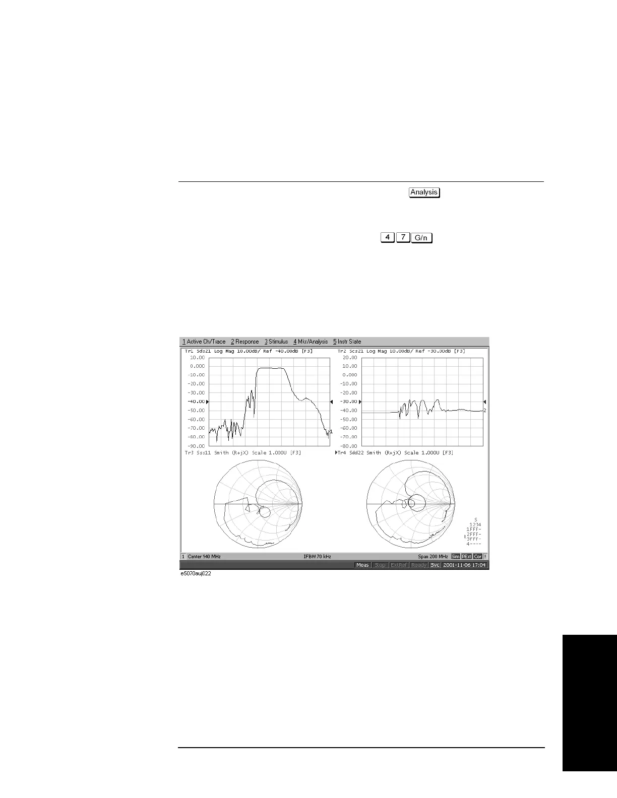
Figure 15-31 shows the results of adding a matching circuit.
Figure 15-31 Results of adding a matching circuit (47 nH)
 Loading...


