50 Chapter 2
Overview of Functions
Screen Area: Names and Functions of Parts
5-6. Reference Line Indicators
The indicators that indicate the position of the reference line for the Y-axis scale in the
rectangular display format. One indicator is to the right and the other is to the left of the
scale (
and ). To enter a numeric value for the position of the reference line, open the
data entry bar using the keys: - Reference Position. You can also move the
position of the reference line by placing the mouse pointer on either of the two reference
line indicators (the pointer changes from
to .), moving the indicator vertically with
the left mouse button kept pressed, and then releasing the button at the desired location
(i.e., a drag-and-drop operation).
5-7. Trace Number
In the rectangular display format, the trace number is displayed in the same color as the
trace at the right end of each trace.
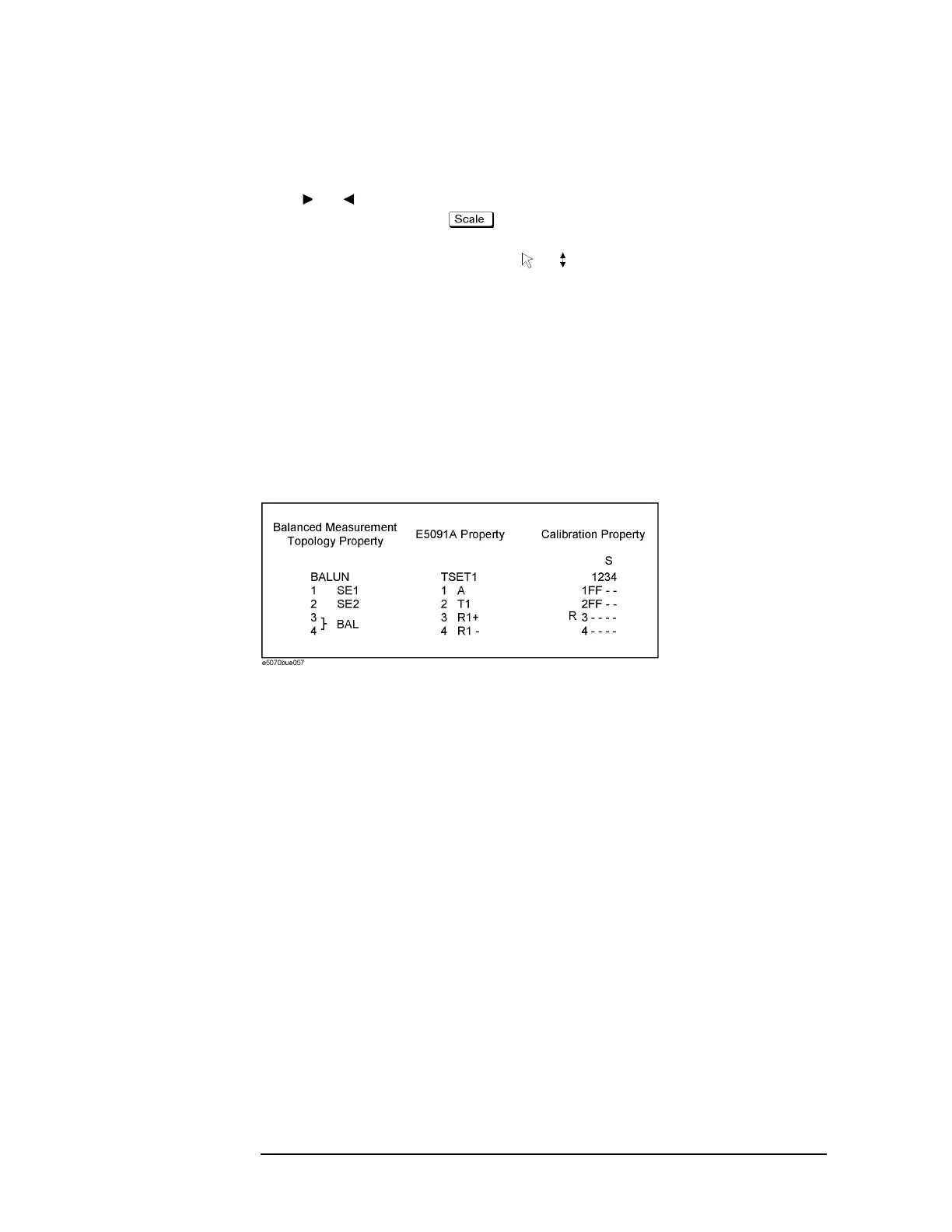
5-8. Properties
Displays the following properties.
Figure 2-7 Properties
Calibration Property Displays the status of the obtained calibration coefficients
on the channel. For details, see
“Acquisition status of
calibration coefficient for each channel” on page 103.
E5091A Property Displays the assignment information of the test ports on the
channel. For details, see
“Displaying the E5091A
properties” on page 479.
Balanced Measurement
Topology Property
Displays the topology for balanced measurement on the
channel. For details, see
“Checking device type and port
assignment” on page 299.
5-9. Channel Status Bar
The status of each channel is displayed here (see parts 5-10 through 5-16).
 Loading...


