ADR233B
Ref ID : ADR233B/IM/PS
Rev No. : 05
Page No. : 130 of 479
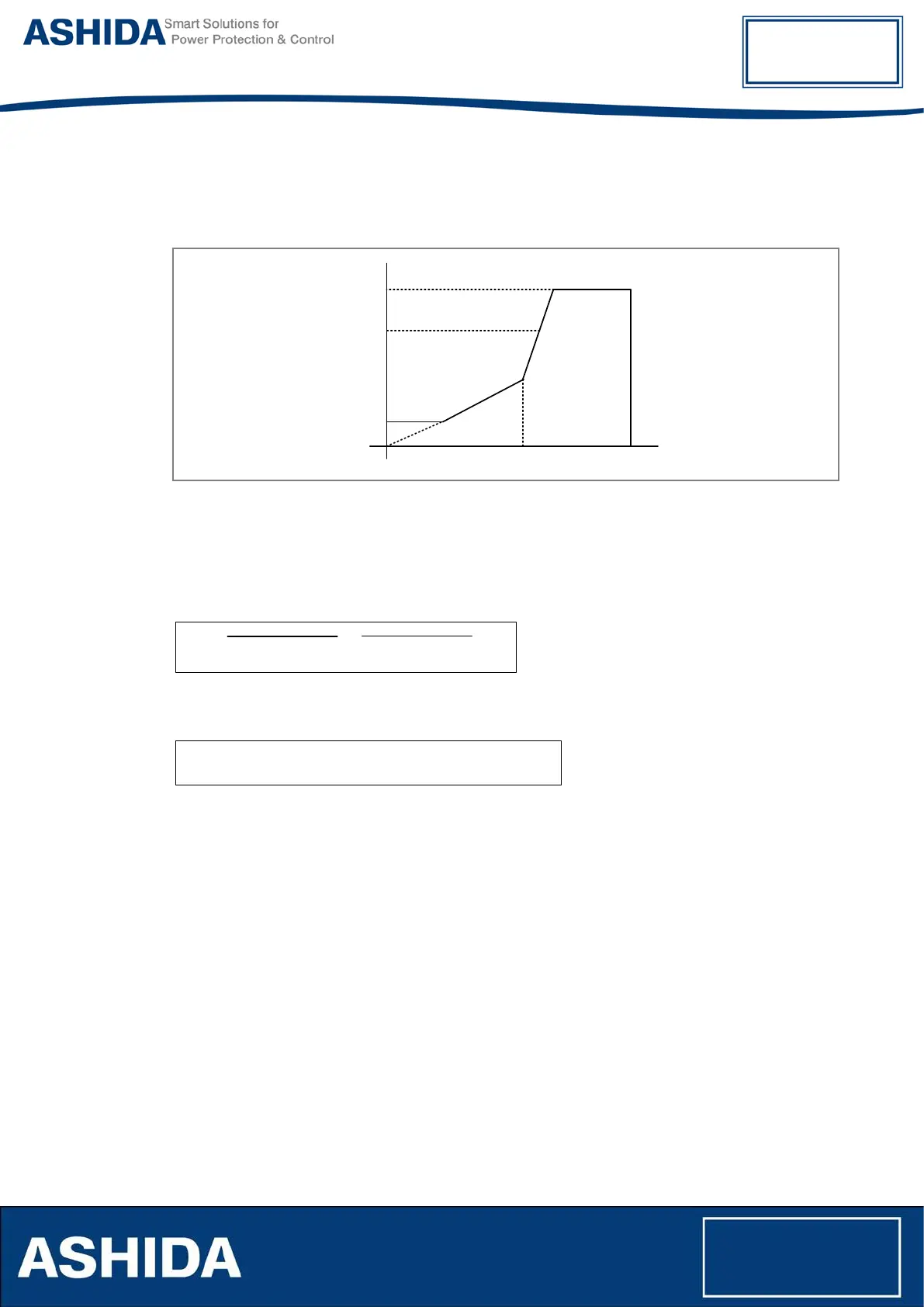
provides stability for low external faults. The higher slope provides stability for high through fault
conditions, since transient differential currents may be present due to current transformer
saturation.
Idiff
IHs>2
IHs>1
Is>1
Operate
Region
Restrain
Region
Is>2
Slope1
Slope2
Ibias
Figure 6: Transformer Differential operating characteristics
The two winding differential and bias currents for each phase are calculated from the current
variables after amplitude and vector group matching as shown below.
DIFFERENTIAL CALCULATION
Idiff
=
W1 Phase Current
+ W2
Phase Current
BIAS CALCULATION
Ibias = (|
W1 Phase Current
|
+
|
W2 Phase Current
|)
/ 2
Once the differential and the bias currents are calculated after amplitude and phase
compensation, the following comparisons are made and an operate/restrain signal is obtained:
For the pickup range: 0 ≤ Ibias max ≤( (Is>1)/slope1)
Idiff ≥ (Is>1)
For the Slope1 slope range: (Is>1/Slope1)≤ Ibias max ≤ Slope2
Idiff ≥ Slope1*Ibias max
For the Slope2 slope range: Is>2 ≤ Ibias max ≤ ((IHs>2)/Slope2)
Idiff ≥ Slope2 * Ibias max + (Slope1 –Slope2) *Is>2
Where;
Idiff and Ibias are calculated current from Winding1 current and Winding 2 current.