ADR233B
Ref ID : ADR233B/IM/PS
Rev No. : 05
Page No. : 152 of 479
4.18 Programmable Logic control
The Basic version of ADR233B relay provides total 8 nos. of target & programmable LEDs with
dual colours indication and 12 Digital inputs and 11 digital outputs.
The Enhanced version of ADR233B relay provides total 16 nos. of target & programmable LEDs
with dual colours indication and 10 Digital inputs and 11/16 digital outputs.
The Basic version of ADR233B relay provides total 16 nos. of target & programmable LEDs with
dual colours indication and maximum 32 Digital inputs and 32 digital outputs.
The LEDs and outputs can be programmed through PC software (RTV2 software).
The ADR233B also provides the programmable pushbuttons for circuit breaker close and open
from HMI of relay. Pushbuttons can be programmed through RTV2 software.
The ADR233B relay integrates complete logic equations to allow Customization of the product
based on customer application. User can program AND/ OR/ XOR/ NOT/ NAND/ NOR/ SR Flip-
flop/ Counter Logic equations with pick up and reset timer at the output. Independent Boolean
equations can be used and every result of equation can be time delayed and assigned to any
output relays and LEDs.
Any protection functions, Control Operations and opto I/Ps are used as inputs to the logic
equations and result of equation can be time delayed and assigned to any output relays and
LEDs.
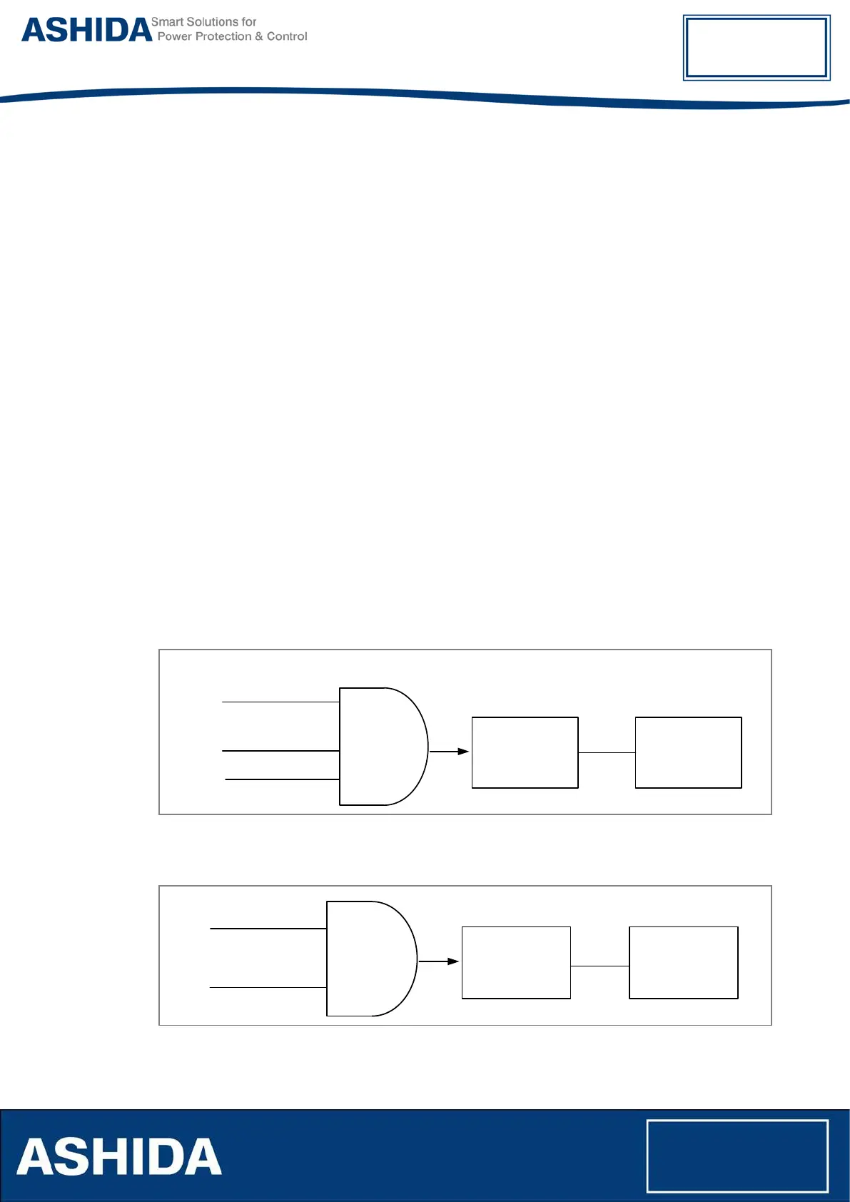
The following example explain AND logic equation.
Pickup
Reset
Timer
Protection
Function
Opto I/P
AND
Gate
Assigned
Relay
Contact /LED
Control
Operation
Figure 29: AND Equation Logic
An example logic implementation using Boolean Equation is shown below:
Pickup
Reset
Timer
TCS Alarm
AND
Gate
Assigned
Relay
Contact /LED
Opto I/P 1
Figure 30: AND Equation Logic Example