ADR233B
Ref ID : ADR233B/IM/PS
Rev No. : 05
Page No. : 139 of 479
3I
0
>n
+
-
&
3
I0
Residual Current
3I
0>
n
= Enable
3
I0
>
n T
3
I0
>
n P
I
DMT
/
DT
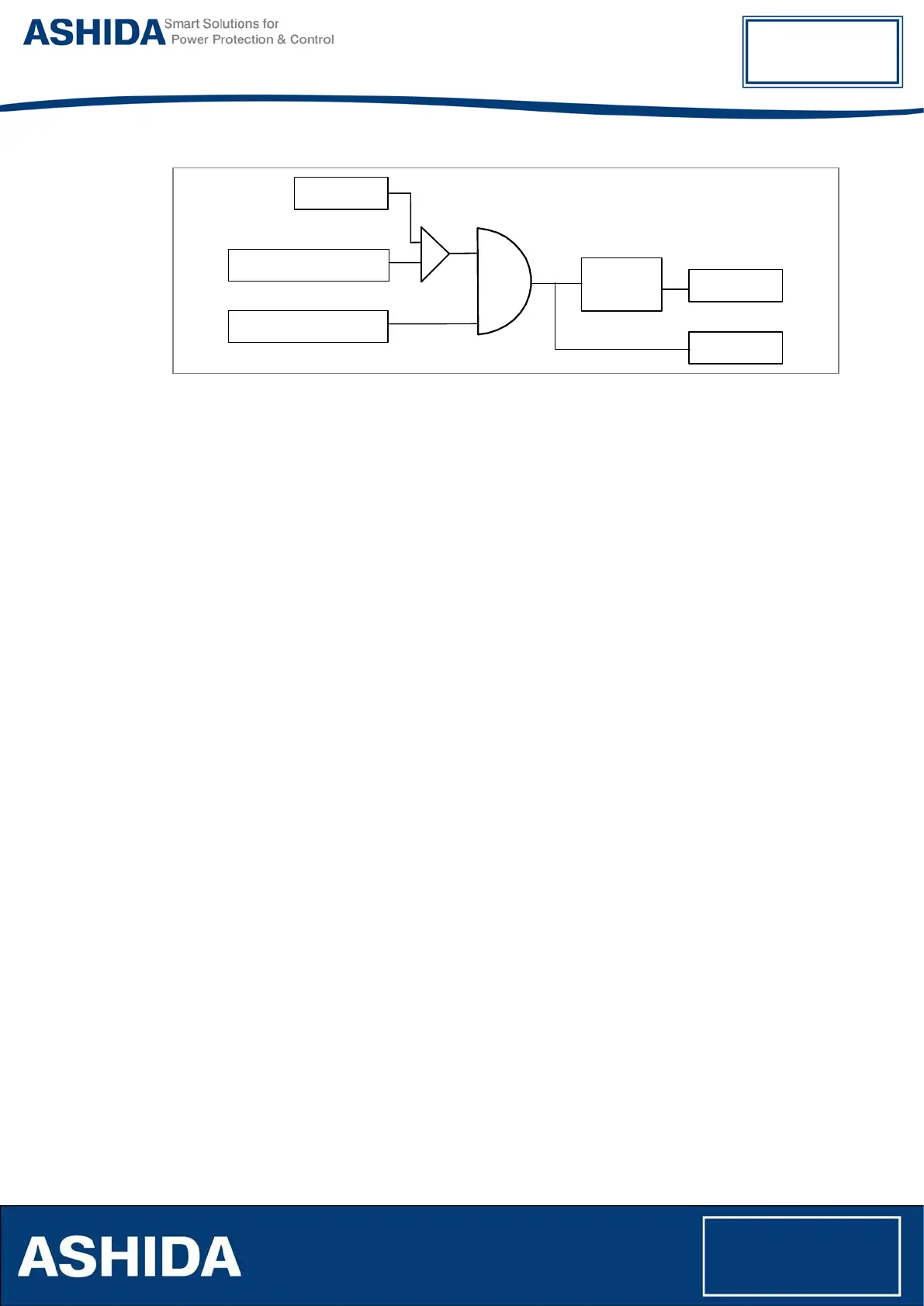
Figure 17: Logic Diagram for the Non Directional Residual over current
Where n=1, 2, 3, stages of Residual Over Current.
The Residual over Current logic checks the Derived Ground currents are exceeds the pickup
value (3I0>n) and calculating the operating time based on the curve selected in the 3I0>n Curve
setting and 3I0>n TMS, 3I0>n Time Dial or t3I0>n DT Delay parameter settings. After satisfied
all the above condition the IED generates the Residual over current trip. Once the Pickup signal
will be asserted then it will reset after the time delay calculated from IDMT/DT dropout
characteristics.
4.12 Sequence Over Current Protection (W1/W2)
ADR233B provides three independent stages of phase sequence over current protection
function. Each stage can be set as Positive sequence or Negative sequence over current
function.
The Positive & Negative sequence current is calculate from the three phase current is shown
below
Positive sequence current I1 = (IA+αIB+α
2
IC)/3
Negative sequence current I2 = (IA+α
2
IB+αIC)/3
Where,
α = ∟120º
α
2
= ∟240º
The below logic diagram fig.18 is work for Negative phase sequence over current protection
function when Seq.I>1 Enable parameter is selected as “-Seq “