ADR233B
Ref ID : ADR233B/IM/PS
Rev No. : 05
Page No. : 138 of 479
IE>n
IN Ground Current
IE
>
n =
Enable
+
-
&
IE>nT
IE
>n P
IDMT/
DT
Figure 15: Logic Diagram for the Non Directional Ground over current
Where n=1, 2, 3 stages of Ground Over Current.
The Ground over Current logic checks the Measured Ground currents are exceeds the pickup
value (IE>n) and calculating the operating time based on the curve selected in the IE>n Curve
setting and IE>n TMS, IE>n Time Dial or tIE>n DT Delay parameter settings. After satisfied all
the above condition the IED generates the Ground over current trip. Once the Pickup signal will
be asserted then it will reset after the time delay calculated from IDMT/DT dropout
characteristics.
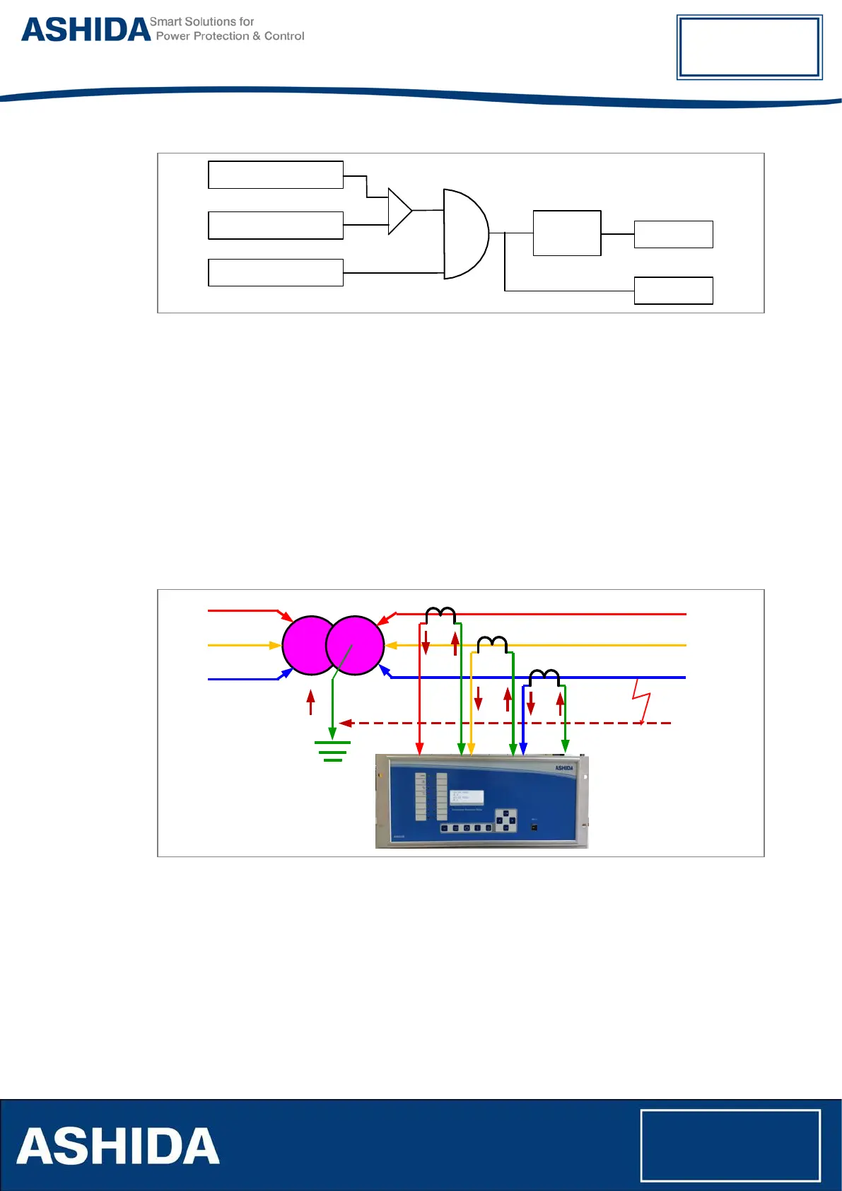
4.11 Non Directional Residual Over current (50N/51N) Protection (W1/W2)
Figure 16: Residual over current from three phases (Derived Zero sequence current)
ADR233B relay provides three independent stages of Residual over current protection function.
The relay derives ground fault current internally through software from the three phase current.
Non directional residual over-current function operates for a set value of current with time delay
(IDMT/DT). The following diagram explains about the Residual over current protection function.