ADR233B
Ref ID : ADR233B/IM/SS
Rev No. : 05
Page No. : 172 of 479
6.8 Group 1 Settings
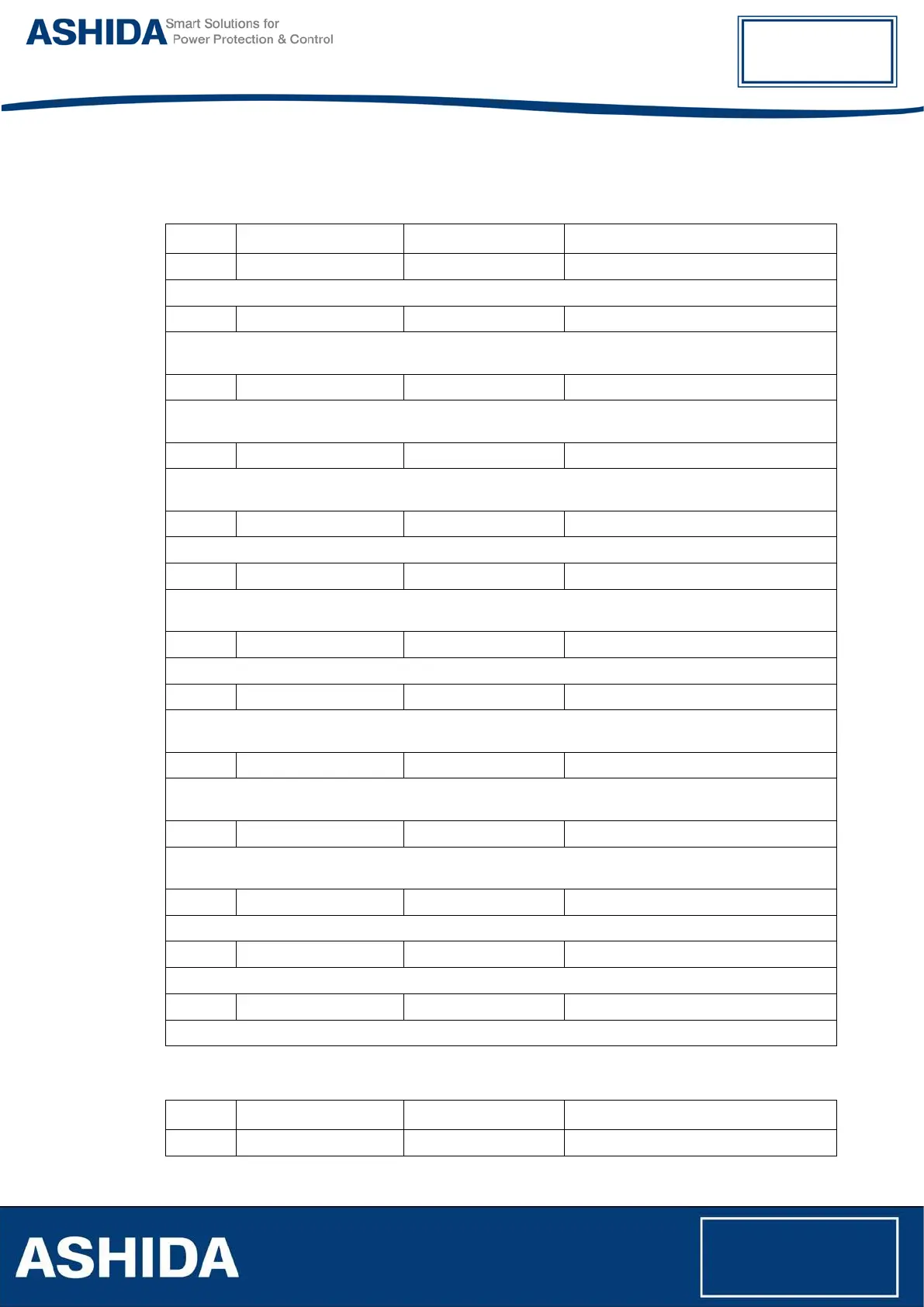
6.8.1 Equipment Data
Sr. No Parameter Defaults setting Settings / Ranges
1. W1 Connection Y-Wye Y-Wye, D-Delta
This setting defines power transformer's W1 winding connection type.
2. W1 Grounding Grounded Grounded / Ungrounded
This setting defines whether the winding is Grounded or not. It defines Zero sequence filtering is required
if it is Grounded and vice a versa.
3. W1 Nominal Range KV V / kV
This setting is to set the range of W1 nominal voltage interims of kV or V. If the nominal voltage is less
than 1000 V then V can be selected, otherwise should select as kV.
4. W1 Nominal 11.0 kV 1.0 kV to 1000.0 kV in step of 0.1kV
This setting shows the voltage of the W1 winding, mid-tap voltage of the on-load tap changer, or no-load
tap changer tap voltage. This setting visible only if W1 Nominal Range is set as kV
5. MVA Rating 100MVA 0.1MVA to 5000MVA in step of 0.1MVA
This rating is to set the MVA rating of Transformer
6. Vector Group 0 0 to 11 in step of 1
This setting defines the vector group of the W2 winding with respect to the reference vector group. It is
used to correct the phase shift between W1 and W2 windings.
7. W2 Connection Y-Wye Y-Wye / D-Delta / Z-Zigzag
This setting defines the power transformer's W2 winding connection type.
8. W2 Grounding Grounded Grounded / Ungrounded
This setting defines whether the winding is Grounded or not. . It defines Zero sequence filtering is
required if it is Grounded and vice a versa.
9. W2 Nominal Range V V / kV
This setting is used to set the range of W2 nominal voltage interims of kV or V. if the nominal voltage is
less than 1000 V then V can be selected, otherwise it should select as kV.
10. W2 Nominal 11.0 kV 1.0 k to 1000.0 kV in step of 0.1kV
This setting shows the voltage of the W2 winding, mid-tap voltage of the on-load tap changer, or no-load
tap changer tap voltage. This setting visible only if W2 Nominal Range is set as kV
11. W1 Match Factor Set by relay Read Only
This setting displays the CT1 ratio correction factor used by the differential function.
12. W2 Match Factor Set by relay Read Only
This setting displays the CT2 ratio correction factor used by the differential function.
13. REF Match Factor Set by relay Read Only
The reference currents for W1 / W2 winding of the protected object are calculated by the relay
6.8.2 Ph Differential
Sr. No Parameter Defaults setting Settings / Ranges
1. Ph Differential Enabled Disabled / Enabled